ACTIVE STABILIZER SUSPENSION SYSTEM TERMINALS OF ECU

-
FRONT ACTIVE STABILIZER CONTROL ECU

Tech Tips
The voltage cannot be measured with the connector connected to the front active stabilizer control ECU as the connector is water resistant.
Terminal No. (Symbols) Wiring Color Terminal Description z67-1 (HC) G C phase input signal (Magnetic pole sensor (Motor pulse sensor)) z67-2 (SR) Y Motor short relay operation signal output (12 V) z67-3 (BSV) BR ECU identification input z67-4 (BSC) BR ECU identification output z67-5 - - z67-6 - - z67-7 (SV) R Magnetic pole sensor (Motor pulse sensor) power source output (12 V) z67-8 (HA) L A phase input signal (Magnetic pole sensor (Motor pulse sensor)) z67-9 (HB) W B phase input signal (Magnetic pole sensor (Motor pulse sensor)) z67-10 - - z67-11 (SHG) B-W Magnetic pole sensor (Motor pulse sensor) shielded line ground z67-12 (SG) B Magnetic pole sensor (Motor pulse sensor) power source circuit ground z68-1 (W) W W phase motor output z68-2 (U) R U phase motor output z68-3 (V) B V phase motor output A75-1 (LCN+) R CAN communication line Hi (steering bus) A75-2 (CANH) Y CAN communication line Hi (braking and driving bus) A75-3 (CANL) L CAN communication line Lo (braking and driving bus) A75-4 (PIG) R Power source (46 V) A75-5 (PGND) W-B Power ground A75-6 - - A75-7 (CT-) W CAN communication line Lo (steering bus) A75-8 (LCN-) G CAN communication line Lo (steering bus) A75-9 (IG) L IG power source A75-10 (CT+) B CAN communication line Hi (steering bus) A75-11 (MRL) W Power supply stop signal output (46 V) -
FRONT ACTIVE STABILIZER CONTROL ACTUATOR
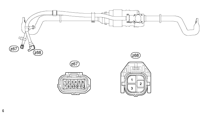
Terminal No. (Symbols) Wiring Color Terminal Description z67-1 (HC) G C phase output signal (Magnetic pole sensor (Motor pulse sensor)) z67-2 (SR) Y Motor short relay operation signal input (12 V) z67-3 (BSV) BR ECU identification output (connected to z67-4 (BSC)) z67-4 (BSC) BR ECU identification input (connected to z67-3 (BSV)) z67-5 - - z67-6 - - z67-7 (SV) R Magnetic pole sensor (Motor pulse sensor) power source input (12 V) z67-8 (HA) L A phase output signal (Magnetic pole sensor (Motor pulse sensor)) z67-9 (HB) W B phase output signal (Magnetic pole sensor (Motor pulse sensor)) z67-10 - - z67-11 (SHG) B-W Magnetic pole sensor (Motor pulse sensor) shielded line ground z67-12 (SG) B Magnetic pole sensor (Motor pulse sensor) power source circuit ground z68-1 (W) W W phase motor input z68-2 (U) R U phase motor input z68-3 (V) B V phase motor input -
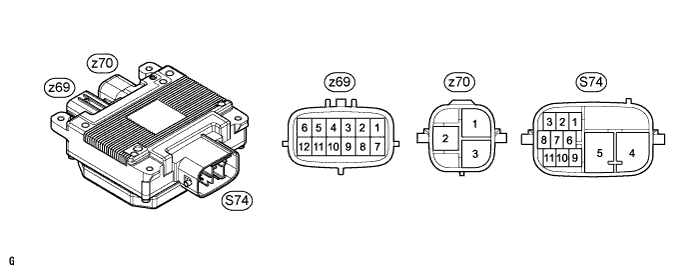
REAR ACTIVE STABILIZER CONTROL ECU
Tech Tips
The voltage cannot be measured with the connector connected to the rear active stabilizer control ECU as the connector is water resistant.
Terminal No. (Symbols) Wiring Color Terminal Description z69-1 (HC) G C phase input signal (Magnetic pole sensor (Motor pulse sensor)) z69-2 (SR) Y Motor short relay operation signal output (12 V) z69-3 - - z69-4 (BSC) - ECU identification output z69-5 (BST) - ECU identification input z69-6 - - z69-7 (SV) R Magnetic pole sensor (Motor pulse sensor) power source output (12 V) z69-8 (HA) L A phase input signal (Magnetic pole sensor (Motor pulse sensor)) z69-9 (HB) W B phase input signal (Magnetic pole sensor (Motor pulse sensor)) z69-10 - - z69-11 (SHG) - Magnetic pole sensor (Motor pulse sensor) shielded line ground z69-12 (SG) B Magnetic pole sensor (Motor pulse sensor) power source circuit ground z70-1 (W) W W phase motor output z70-2 (U) R U phase motor output z70-3 (V) B V phase motor output S74-1 (LCN+) B CAN communication line Hi (steering bus) S74-2 (CANH) Y CAN communication line Hi (braking and driving bus) S74-3 (CANL) L CAN communication line Lo (braking and driving bus) S74-4 (PIG) B Power source (46 V) S74-5 (PGND) W-B Power ground S74-6 (MRH) L Power steering converter condition signal input S74-7 - - S74-8 (LCN-) W CAN communication line Lo (steering bus) S74-9 (IG) G IG power source S74-10 - - S74-11 (MRL) R Power supply stop signal output (46 V) -
REAR ACTIVE STABILIZER CONTROL ACTUATOR
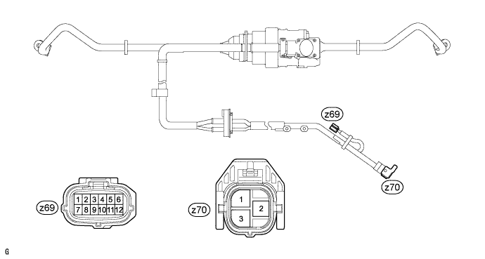
Terminal No. (Symbols) Wiring Color Terminal Description z69-1 (HC) G C phase output signal (Magnetic pole sensor (Motor pulse sensor)) z69-2 (SR) Y Motor short relay operation signal input (12 V) z69-3 - - z69-4 (BSC) - ECU identification input (connected to z69-5 (BST)) z69-5 (BST) - ECU identification output (connected to z69-4 (BSC)) z69-6 - - z69-7 (SV) R Magnetic pole sensor (Motor pulse sensor) power source input (12 V) z69-8 (HA) L A phase output signal (Magnetic pole sensor (Motor pulse sensor)) z69-9 (HB) W B phase output signal (Magnetic pole sensor (Motor pulse sensor)) z69-10 - - z69-11 (SHG) - Magnetic pole sensor (Motor pulse sensor) shielded line ground z69-12 (SG) B Magnetic pole sensor (Motor pulse sensor) power source circuit ground z70-1 (W) W W phase motor input z70-2 (U) R U phase motor input z70-3 (V) B V phase motor input -
POWER STEERING CONVERTER
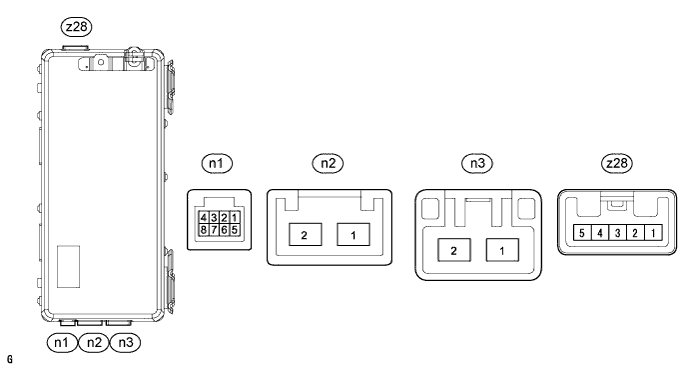
Terminal No. (Symbols) Wiring Color Terminal Description n1-1 (WDD1) G Power steering converter condition signal output to power steering ECU n1-2 (WDD3) L Power steering converter condition signal output to active stabilizer control ECU n1-3 (DRSF) W 46 V power supply stop signal input from front active stabilizer control ECU n1-4 (DRSR) R 46 V power supply stop signal input from rear active stabilizer control ECU n1-5 (IG) Y IG power source n1-6 (DDOK) V High voltage use permission signal input from hybrid vehicle control ECU n1-7 (ASST) SB 46 V power supply output from power steering ECU n1-8 (GND) W-B Ground n2-1 (PIG) B Backup power supply input (12 V) of power steering system n2-2 (VGND) W-B Ground n3-1 (VOT1) B 46 V power supply output to power steering ECU n3-2 (VOT2) R 46 V power supply output to active stabilizer control ECU z28-1 (CBP) R 46 V power supply output to active stabilizer control ECU z28-2 - - z28-3 - - z28-4 - - z28-5 (CEP) L HV battery negative (-) power supply