ACTIVE STABILIZER SUSPENSION SYSTEM, Diagnostic DTC:C1929, C192A, C192B, C192C, C1944

| DTC Code | DTC Name |
|---|---|
| C1929 | Front Magnetic Pole Sensor Initialization Incomplete |
| C192A | Front Magnetic Pole Sensor Pattern |
| C192B | Front Actuator Short Detect Relay |
| C192C | Protection for Overload of Front Actuator |
| C1944 | Front Actuator Torque Decrease |
DESCRIPTION
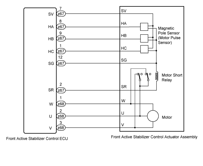
If a malfunction occurs in the front active stabilizer control actuator's magnetic pole sensor (rotation position sensor), the motor short relay or the motor short relay's circuit, DTC C1929, C192A, C192B, C192C and/or C1944 are output.
| DTC Code | Detection Condition | Trouble Area |
|---|---|---|
| C1929 | During initial check immediately after turning power switch ON (READY), malfunction is detected in front active stabilizer control actuator's magnetic pole sensor (motor pulse sensor) |
|
| C192A | Malfunction is detected in front active stabilizer control actuator's magnetic pole sensor (motor pulse sensor) | |
| C192B | Malfunction is detected in front active stabilizer control actuator's motor short relay | |
| C192C | During front active stabilizer control, front active stabilizer control actuator stuck condition is detected | |
| C1944 | During front active stabilizer control, front active stabilizer control actuator torque insufficient condition is detected |
WIRING DIAGRAM
INSPECTION PROCEDURE
PROCEDURE
-
CHECK CONNECTOR CONNECTION CONDITION
-
Turn the power switch OFF.
-
Inspect the condition of the z67 and z68 connector terminals.
OK Connector and terminal are not deformed or damaged. Terminal is not loose or corroded. Tech Tips
The harness from the front active stabilizer control actuator to the front active stabilizer control ECU is part of the front active stabilizer control actuator. If the harness is damaged and cannot be repaired, replace the front active stabilizer control actuator assembly Click here.
NG 
REPAIR OR REPLACE HARNESS OR CONNECTOR
OK 
-
-
INTERCHANGE FRONT AND REAR ACTIVE STABILIZER CONTROL ECU ASSEMBLY
-
Turn the power switch OFF.
-
Interchange the front active stabilizer control ECU with the rear active stabilizer control ECU, and install them securely.
Tech Tips
-
Interchange the front and rear active stabilizer control ECUs and check for DTCs. After interchanging the ECUs, if a rear stabilizer DTC is displayed, it can be determined that the front active stabilizer control ECU is malfunctioning. If no DTC is output, the front active stabilizer control actuator is malfunctioning.
-
For the ECU removal and installation procedures, refer to the front ECU procedures Click here or the rear ECU procedures Click here.
-
NEXT
-
-
CLEAR DTC
-
Turn the power switch OFF.
-
Connect the intelligent tester to the DLC3.
-
Turn the power switch ON (IG) and the tester ON.
-
Clear the DTC Click here.
NEXT
-
-
CHECK OPERATION OF FRONT ACTIVE STABILIZER CONTROL ECU ASSEMBLY
-
Turn the power switch OFF.
-
Connect the intelligent tester to the DLC3.
-
Turn the power switch ON (READY) and wait 30 seconds or more. Then check for rear stabilizer DTCs Click here.
OK DTC C1901, C1902, C1903, C1904 and C191C are not output.
NG
REPLACE FRONT ACTIVE STABILIZER CONTROL ECU ASSEMBLY Click here
OK 
REPLACE FRONT ACTIVE STABILIZER CONTROL ACTUATOR ASSEMBLY Click here
-