AIR SUSPENSION SYSTEM, Diagnostic DTC:C1731, C1732, C1733, C1734

| DTC Code | DTC Name |
|---|---|
| C1731 | Front Damping Force Control Actuator RH Circuit Malfunction |
| C1732 | Front Damping Force Control Actuator LH Circuit Malfunction |
| C1733 | Rear Damping Force Control Actuator RH Circuit Malfunction |
| C1734 | Rear Damping Force Control Actuator LH Circuit Malfunction |
DESCRIPTION
The absorber control actuator switches the damping force depending on the suspension control ECU signals.
| DTC No. | Detection Condition | Trouble Area |
|---|---|---|
| C1731 | When either of the following is detected:
|
|
| C1732 | When either of the following is detected:
|
|
| C1733 | When either of the following is detected:
|
|
| C1734 | When either of the following is detected:
|
|
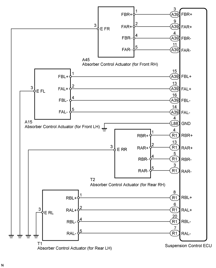
WIRING DIAGRAM
INSPECTION PROCEDURE
Note
-
Before performing troubleshooting, inspect the connectors of related circuits.
-
If DTC C1782 (Power Source Voltage Malfunction) is output at the same time, perform troubleshooting for C1782 first Click here.
-
Before replacing the suspension control ECU, perform all of the following again: 1) symptom simulation Click here; 2) DTC inspection; and 3) intelligent tester inspection (Data List or Active Test). If no malfunctions are found in other areas, replace the suspension control ECU.
-
If the suspension control ECU or height control sensor is replaced, the vehicle height offset calibration must be performed Click here.
PROCEDURE
-
CLEAR DTC
-
Clear the DTC Click here.
NEXT 
-
-
CHECK ABSORBER CONTROL ACTUATOR OPERATION (ACTIVE TEST)
-
Turn the power switch OFF.
-
Connect the intelligent tester to the DLC3.
-
Turn the power switch ON (IG) and the tester ON.
-
Enter the following menus: Chassis / Air suspension / Active Test.
-
According to the display on tester, perform the "Active Test".
-
Check if the absorber control actuator operates to harden the suspension with the intelligent tester.
Air suspension Tester Display Test Part Control Range Diagnostic Note Damper Step FR Changes front damper RH step min.: 1 step
max.: 17 step
Shock absorber hardens as damper step increases Damper Step FL Changes front damper LH step min.: 1 step
max.: 17 step
Shock absorber hardens as damper step increases Damper Step RR Changes rear damper RH step min.: 1 step
max.: 17 step
Shock absorber hardens as damper step increases Damper Step RL Changes rear damper LH step min.: 1 step
max.: 17 step
Shock absorber hardens as damper step increases OK The absorber control actuator operates.
NG 
INSPECT ABSORBER CONTROL ACTUATOR OF WHEEL TO BE INSPECTED Click here
OK 
USE SIMULATION METHOD TO CHECK Click here
-
-
INSPECT ABSORBER CONTROL ACTUATOR OF WHEEL TO BE INSPECTED
-
Remove the absorber control actuator, for front side Click here or for rear side Click here.
-

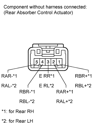
Measure the resistance according to the value(s) in the table below.
Standard resistance for Front RH: (C1731) Tester Connection Condition Specified Condition 1 (FBR+) - 3 (E FR) Always 12.0 to 12.8 Ω 2 (FAR+) - 3 (E FR) Always 12.0 to 12.8 Ω 4 (FBR-) - 3 (E FR) Always 12.0 to 12.8 Ω 5 (FAR-) - 3 (E FR) Always 12.0 to 12.8 Ω for Front LH: (C1732) Tester Connection Condition Specified Condition 1 (FBL+) - 3 (E FL) Always 12.0 to 12.8 Ω 2 (FAL+) - 3 (E FL) Always 12.0 to 12.8 Ω 4 (FBL-) - 3 (E FL) Always 12.0 to 12.8 Ω 5 (FAL-) - 3 (E FL) Always 12.0 to 12.8 Ω Standard resistance for Rear RH: (C1733) Tester Connection Condition Specified Condition 1 (RBR+) - 3 (E RR) Always 12.0 to 12.8 Ω 2 (RAR+) - 3 (E RR) Always 12.0 to 12.8 Ω 4 (RBR-) - 3 (E RR) Always 12.0 to 12.8 Ω 5 (RAR-) - 3 (E RR) Always 12.0 to 12.8 Ω for Rear LH: (C1734) Tester Connection Condition Specified Condition 1 (RBL+) - 3 (E RL) Always 12.0 to 12.8 Ω 2 (RAL+) - 3 (E RL) Always 12.0 to 12.8 Ω 4 (RBL-) - 3 (E RL) Always 12.0 to 12.8 Ω 5 (RAL-) - 3 (E RL) Always 12.0 to 12.8 Ω Result Result Proceed to OK A Absorber control actuator (for Front RH) malfunction B Absorber control actuator (for Front LH) malfunction C Absorber control actuator (for Rear RH) malfunction D Absorber control actuator (for Rear LH) malfunction E
B 
REPLACE ABSORBER CONTROL ACTUATOR Click here
C
REPLACE ABSORBER CONTROL ACTUATOR Click here
D
REPLACE ABSORBER CONTROL ACTUATOR Click here
E
REPLACE ABSORBER CONTROL ACTUATOR Click here
A
-
-
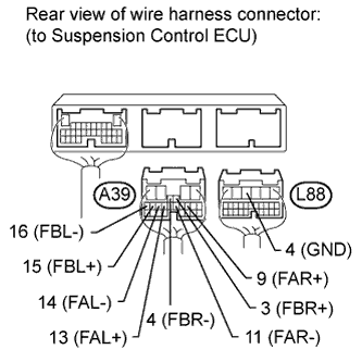
CHECK HARNESS AND CONNECTOR (ABSORBER CONTROL ACTUATOR - ECU AND BODY GROUND)
-
Check the front side absorber control actuator.
-
Connect the A15 or A45 front absorber control actuator connector.
-
Disconnect the A39 and L88 ECU connectors.
-
Measure the resistance according to the value(s) in the table below.
Standard resistance for Front RH: (C1731) Tester Connection Condition Specified Condition A39-3 (FBR+) - L88-4 (GND) Always 12.0 to 12.8 Ω A39-4 (FBR-) - L88-4 (GND) Always 12.0 to 12.8 Ω A39-9 (FAR+) - L88-4 (GND) Always 12.0 to 12.8 Ω A39-11 (FAR-) - L88-4 (GND) Always 12.0 to 12.8 Ω for Front LH: (C1732) Tester Connection Condition Specified Condition A39-13 (FAL+) - L88-4 (GND) Always 12.0 to 12.8 Ω A39-14 (FAL-) - L88-4 (GND) Always 12.0 to 12.8 Ω A39-15 (FBL+) - L88-4 (GND) Always 12.0 to 12.8 Ω A39-16 (FBL-) - L88-4 (GND) Always 12.0 to 12.8 Ω
-
-
Check the rear side absorber control actuator.
-
Connect the T1 or T2 rear absorber control actuator connector.
-
Disconnect the R1 and L88 ECU connectors.
-
Measure the resistance according to the value(s) in the table below.
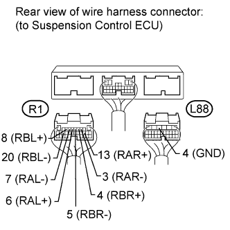
Standard resistance for Rear RH: (C1733) Tester Connection Condition Specified Condition R1-3 (RAR-) - L88-4 (GND) Always 12.0 to 12.8 Ω R1-4 (RBR+) - L88-4 (GND) Always 12.0 to 12.8 Ω R1-5 (RBR-) - L88-4 (GND) Always 12.0 to 12.8 Ω R1-13 (RAR+) - L88-4 (GND) Always 12.0 to 12.8 Ω for Rear LH: (C1734) Tester Connection Condition Specified Condition R1-6 (RAL+) - L88-4 (GND) Always 12.0 to 12.8 Ω R1-7 (RAL-) - L88-4 (GND) Always 12.0 to 12.8 Ω R1-8 (RBL+) - L88-4 (GND) Always 12.0 to 12.8 Ω R1-20 (RBL-) - L88-4 (GND) Always 12.0 to 12.8 Ω Result Result Proceed to NG A OK (for LHD) B OK (for RHD) C
-
B
REPLACE SUSPENSION CONTROL ECU Click here
C
REPLACE SUSPENSION CONTROL ECU Click here
A
REPAIR OR REPLACE HARNESS OR CONNECTOR
-