DIFFERENTIAL CARRIER ASSEMBLY REASSEMBLY

-
INSTALL DIFFERENTIAL RING GEAR
-
Clean the differential ring gear set bolt hole.
-
Heat the ring gear to approximately 100°C (212°F) in boiling water.
CAUTION:
Use thick gloves to protect your hands as the ring gear is hot.
-
Carefully take the ring gear out of the boiling water.
-
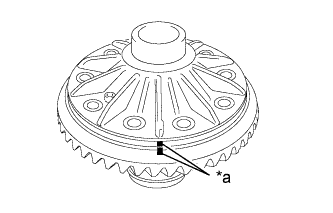
Text in Illustration *a Matchmark After the moisture on the ring gear has completely evaporated, quickly install the ring gear to the differential case with matchmarks aligned.
Note
Make sure there is no oil on the differential case and ring gear contact surfaces.
Tech Tips
Align the rear differential case bolt holes and differential ring gear screw holes.
-
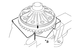
Text in Illustration *a Aluminum Plate Hold the differential case in a vise between aluminum plates.
Note
Do not overtighten the vise.
-
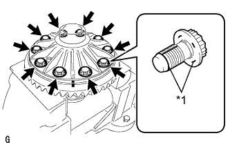
Text in Illustration *1 Thread Lock Apply thread lock adhesive to the threads and flanges of 10 new differential case bolts.
Adhesive Toyota Genuine Adhesive 1360K, Three Bond 1360K or equivalent Note
-
As the differential case bolts are plastic region tightening bolts, do not reuse them.
-
Make sure there is no oil on the threaded parts.
-
-
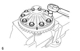
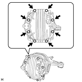
Temporarily tighten the 10 differential case bolts uniformly in several passes, and then tighten them to the torque specification.
- Torque:
- 64 N*m { 653 kgf*cm, 47 ft.*lbf }
Note
-
Tighten the bolts after the ring gear has sufficiently cooled down.
-
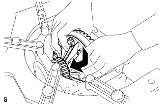
Install the differential case bolts by tightening diametrically opposite pairs uniformly in several passes.
-
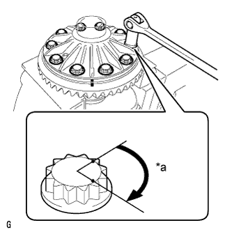
Text in Illustration *a 60° to 90° Tighten the bolts further by 60 to 90°.
Note
Tighten the bolts in diametrically opposite pairs.
-
-
INSTALL REAR DIFFERENTIAL CASE BEARING INNER RACE
-
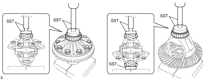
Using SST and a press, press in the case bearing inner race LH and RH to the differential case.
- SST
- 09950-60010 ( 09951-00560, 09951-00570 )
- 09950-70010 ( 09951-07100 )
Note
-
When installing a new bearing, do not wipe off the anti-rust oil.
-
Do not apply hypoid gear oil to a new bearing.
-
Do not deform the bearing cage. Set SST to the center of the differential case.
-
If the bearing is replaced, replace it with the bearing outer race and inner race as a set.
-
-
INSTALL REAR DRIVE PINION REAR TAPERED ROLLER BEARING INNER RACE
-
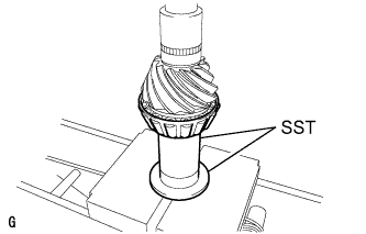
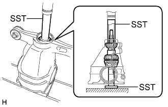
Using SST and a press, press in the rear drive pinion rear tapered roller bearing inner race to the drive pinion.
- SST
- 09316-60011 ( 09316-00031 )
- 09612-10093 ( 09613-22011 )
Note
-
When installing a new bearing, do not wipe off the anti-rust oil.
-
Do not apply hypoid gear oil to a new bearing.
Tech Tips
Disassemble SST (09613-22011), and only use the pipe part.
-
-
REMOVE REAR DRIVE PINION REAR TAPERED ROLLER BEARING OUTER RACE
-
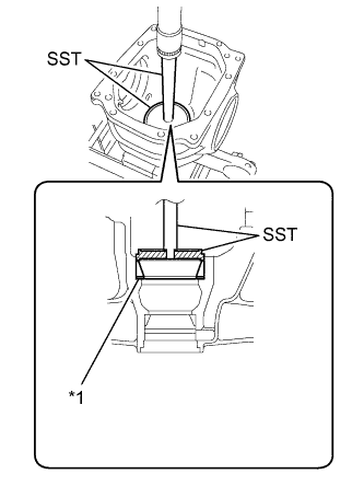
Text in Illustration *1 Differential Drive Pinion Washer Using SST and a press, press in the rear drive pinion rear tapered roller bearing outer race and drive pinion washer.
- SST
- 09255-10012
- 09950-70010 ( 09951-07200 )
Note
-
When installing a new bearing, do not wipe off the anti-rust oil.
-
Do not apply hypoid gear oil to a new bearing.
Tech Tips
Select a drive pinion washer of the same thickness as the one removed.
-
-
INSTALL REAR DRIVE PINION FRONT TAPERED ROLLER BEARING OUTER RACE
-
Using SST and a press, press in the rear drive pinion front tapered roller bearing outer race.
- SST
- 09950-60020 ( 09951-00710 )
- 09950-70010 ( 09951-07100 )
Note
-
When installing a new bearing, do not wipe off the anti-rust oil.
-
Do not apply hypoid gear oil to a new bearing.
-
-
INSTALL REAR DIFFERENTIAL DUST DEFLECTOR
Tech Tips
Perform this procedure only when replacing the dust deflector.
-
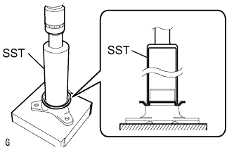
Using SST and a press, insert a new dust deflector into the companion flange.
- SST
- 09316-60011 ( 09316-00011 )
Note
-
Slowly press in the dust deflector but not excessively.
-
If any burrs remain after pressing in the deflector, remove them.
-
-
INSTALL REAR DRIVE PINION FRONT TAPERED ROLLER BEARING INNER RACE
-
Install the rear drive pinion front tapered roller bearing inner race to the differential carrier.
Note
-
When installing a new bearing, do not wipe off the anti-rust oil.
-
Do not apply hypoid gear oil to a new bearing.
-
-
-
INSTALL DIFFERENTIAL DRIVE PINION
-
Using SST and a press, press in the drive pinion.
- SST
- 09608-04031
- 09316-60011 ( 09316-00011, 09316-00041 )
Note
Do not forcefully press in the bearing.
Tech Tips
-
Install the spacer and oil seal after performing the ring gear tooth contact pattern inspection adjustment.
-
Make sure the press, SST and drive pinion are in a straight line when pressing.
-
-
INSTALL REAR DIFFERENTIAL DRIVE PINION OIL SLINGER
-
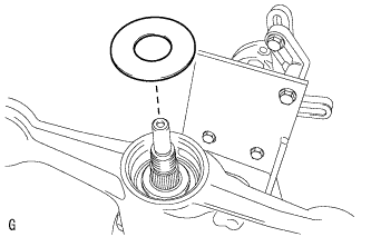
Install the drive pinion oil slinger to the differential carrier.
-
-
ADJUST DIFFERENTIAL DRIVE PINION PRELOAD
-
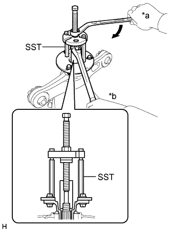
Text in Illustration *a Turn *b Hold Using SST, install the companion flange.
- SST
- 09950-30012 ( 09951-03010, 09954-03010, 09955-03040, 09956-03060 )
Note
Install the companion flange so that there is a slight looseness on the drive pinion because the bearing spacer is not yet installed.
Tech Tips
Before using SST center bolt, apply hypoid gear oil to its threads and tip.
-
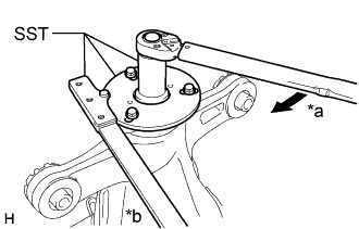
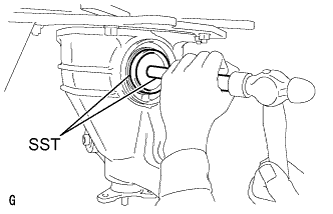
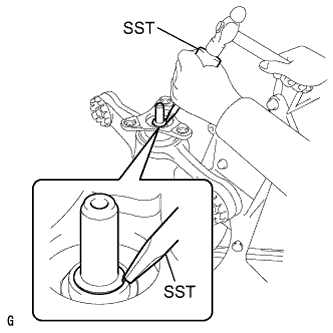
Using SST and a torque wrench, tighten a new drive pinion nut so that the drive pinion preload (starting torque) value is within the torque specification.
- SST
- 09229-55010
- 09330-00021
- 09950-30012 ( 09955-03040 )
Maximum torque 490 N*m (5000 kgf*cm, 361 ft.*lbf) or less Note
-
As the bearing spacer is not installed, tighten the drive pinion nut little by little. Do not overtighten the nut.
-
Do not overtighten the nut, as the threads will become damaged.
-
Perform the installation while supporting the overhaul attachment.
Tech Tips
-
Tighten the nut with a force of 100 N*m (1020 kgf*cm, 74 ft.*lbf) while checking the starting torque of the drive pinion.
-
Coat the threads of the drive pinion nut and drive pinion with hypoid gear oil LSD.
-
For a more accurate measurement, rotate the bearing forward and backward before the inspection.
-
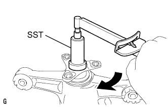
Using SST and a torque wrench, measure the preload.
- SST
- 09229-55010
Standard drive pinion preload (at starting) 1.15 to 1.55 N*m (12 to 15 kgf*cm, 11 to 13 in.*lbf) Note
Record the preload for total preload measurement.
-
-
INSTALL REAR DIFFERENTIAL CASE SUB-ASSEMBLY
-
Insert the differential case from the ring gear tooth side to install it.
Note
Do not damage the case bearing and ring gear.
-
-
INSTALL REAR DIFFERENTIAL CASE BEARING OUTER RACE
-
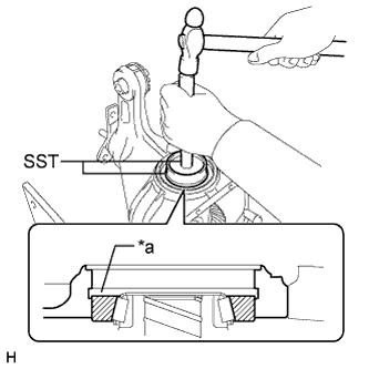
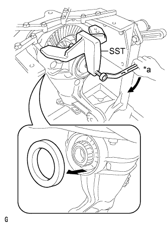
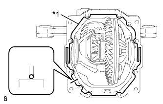
Text in Illustration *a Groove Using SST and a hammer, tap in the ring gear tooth side case bearing outer race.
- SST
- 09608-32010
- 09950-70010 ( 09951-07200 )
Note
-
When installing a new bearing, do not wipe off the anti-rust oil.
-
Do not apply hypoid gear oil to a new bearing.
Tech Tips
Tap in the case bearing outer race until half of the side gear shaft snap ring groove of the differential carrier can be seen.
-

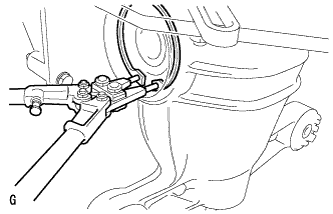
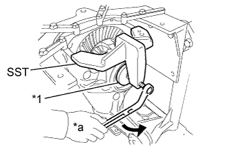
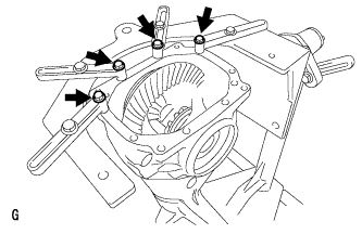
Text in Illustration *1 Disc Install the 2 bolts and SST to the differential carrier.
- SST
- 09571-50010
-
Tighten SST bolt until SST disc lightly touches the case bearing outer race.
-
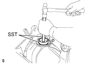
Using SST and a hammer, tap in the ring gear back surface side case bearing outer race.
- SST
- 09608-32010
- 09950-70010 ( 09951-07200 )
Note
-
When installing a new bearing, do not wipe off the anti-rust oil.
-
Do not apply hypoid gear oil to a new bearing.
Tech Tips
Tap in the case bearing outer race until it touches the case bearing inner race roller bearing.
-
-
ADJUST DIFFERENTIAL RING GEAR BACKLASH
-
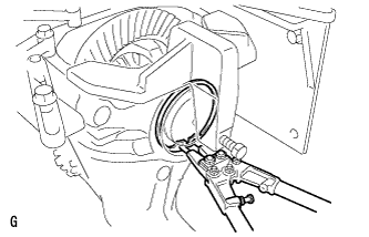
Using snap ring pliers, install a side gear shaft snap ring on the back surface of the ring gear.
If the final gear set (drive pinion and ring gear) or differential case bearing are replaced, select and install the thinnest differential side gear shaft snap ring first.
If the differential case bearing, ring gear, or drive pinion are reused, select and install a differential side gear shaft snap ring with the same thickness as the one before the disassembly first.
-
Install a dial indicator to the differential carrier.
-
Tighten SST bolt to alter the differential carrier's shape by approximately 0.1 mm (0.00394 in.).
- SST
- 09571-50010
Note
Observe the dial indicator to ensure that the shape of the differential carrier does not change more than 0.2 mm (0.00787 in.).
Tech Tips
-
Try to set the dial indicator as close as possible to the differential carrier cover side (upper side in illustration) of the differential case bearing outer race.
-
Tighten SST bolt to apply the preload to the case bearing.
-
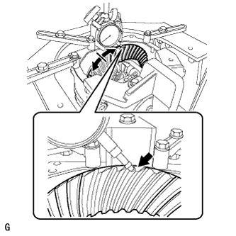
Turn the ring gear clockwise and counterclockwise several times to stabilize the differential case bearing.
-
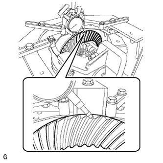
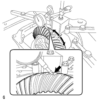
Using a dial indicator, measure the backlash of the ring gear.
Standard backlash 0.08 to 0.13 mm (0.00315 to 0.00511 in.) Tech Tips
-
Measure at 3 or more areas around the circumference of the ring gear.
-
Record the measured value, as it is used to select the differential side gear shaft snap ring.
-
Perform the tooth contact pattern inspection for the differential ring gear and drive pinion. The results will be used as a reference for selecting the differential side gear shaft snap ring.
If the measured value is not within the specified range, replace the ring gear side differential side gear shaft snap ring with one of a different thickness in the a following steps.
-
-

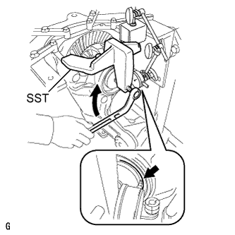
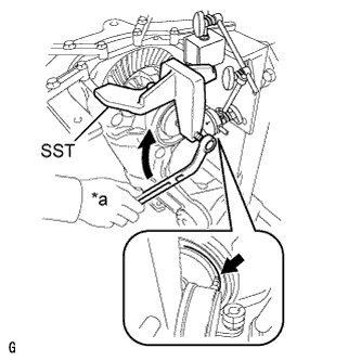
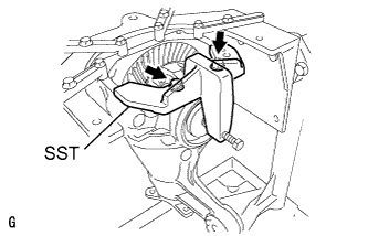
Text in Illustration *1 Disc *a Turn Loosen SST bolt until SST disc separates from the tooth side of the differential case bearing outer race.
-
Using SST and a hammer, tap the ring gear back surface side to create clearance between the differential case bearing outer race and the differential side gear shaft snap ring of the ring gear back surface side.
- SST
- 09608-32010
- 09950-70010 ( 09951-07200 )
Tech Tips
The clearance is not visible, but tapping SST with a hammer 3 or 4 times should be enough.
-
Using snap ring pliers, remove the side gear shaft snap ring on the ring gear back surface side.
-
Using snap ring pliers, install a side gear shaft snap ring with a different thickness than the one removed.
Tech Tips
When the side gear shaft snap ring thickness changes by 0.02 mm (0.000787 in.), the backlash also changes by 0.02 mm (0.000787 in.).
Standard snap ring thickness Thickness Thickness Thickness 3.66 mm (0.1441 in.) 3.92 mm (0.1543 in.) 4.18 mm (0.1646 in.) 3.68 mm (0.1449 in.) 3.94 mm (0.1551 in.) 4.20 mm (0.1654 in.) 3.70 mm (0.1457 in.) 3.69 mm (0.1559 in.) 4.22 mm (0.1661 in.) 3.72 mm (0.1465 in.) 3.98 mm (0.1567 in.) 4.24 mm (0.1669 in.) 3.74 mm (0.1472 in.) 4.00 mm (0.1575 in.) 4.26 mm (0.1677 in.) 3.76 mm (0.1480 in.) 4.02 mm (0.1583 in.) 4.28 mm (0.1685 in.) 3.78 mm (0.1488 in.) 4.04 mm (0.1591 in.) 4.30 mm (0.1693 in.) 3.80 mm (0.1496 in.) 4.06 mm (0.1598 in.) 4.32 mm (0.1701 in.) 3.82 mm (0.1503 in.) 4.08 mm (0.1606 in.) 4.34 mm (0.1709 in.) 3.84 mm (0.1512 in.) 4.10 mm (0.1614 in.) 4.36 mm (0.1717 in.) 3.86 mm (0.1520 in.) 4.12 mm (0.1622 in.) 4.38 mm (0.1724 in.) 3.88 mm (0.1528 in.) 4.14 mm (0.1630 in.) 4.40 mm (0.1732 in.) 3.90 mm (0.1535 in.) 4.16 mm (0.1638 in.) 4.42 mm (0.1740 in.) -
Using a plastic-faced hammer, lightly tap the ring gear tooth side of the differential carrier to stabilizer the differential case bearing.
-
Text in Illustration *a Turn Install a dial indicator to the differential carrier.
-
Tighten SST bolt to alter the differential carrier's shape approximately 0.1 mm (0.00394 in.).
- SST
- 09571-50010
Note
Observe the dial indicator to ensure that the shape of the differential carrier does not change more than 0.2 mm (0.00787 in.)
Tech Tips
-
Try to set the dial indicator as close as possible to the differential carrier cover side (upper side in illustration) of the differential case bearing outer race.
-
Tighten SST bolt to apply the preload to the case bearing.
-
Place a dial indicator so that it is perpendicular to the top of the ring gear on the tooth side.
-
Fix the companion flange in place by hand, and measure the ring gear backlash.
Standard backlash 0.08 to 0.13 mm (0.00315 to 0.00511 in.) Tech Tips
-
Measure at 3 or more areas around the circumference of the ring gear.
-
Record the measured value, as it is used to select the differential side gear shaft snap ring.
-
Perform the tooth contact pattern inspection for the differential ring gear and drive pinion. The results will be used as a reference for selecting the differential side gear shaft snap ring.
-
When adjusting the backlash, adjust to within 0.1 mm (0.00394 in.) of the average of the measurements.
If the measured value is not within the specified range, replace the ring gear back surface side differential side gear shaft snap ring with one of a different thickness.
-
-
-
ADJUST DIFFERENTIAL SIDE BEARING PRELOAD
-
Install a dial indicator to the differential carrier.
-
Tighten SST bolt to alter the differential carrier's shape by approximately 0.1 mm (0.00394 in.).
- SST
- 09571-50010
Note
Observe the dial indicator to ensure that the shape of the differential carrier does not change more than 0.2 mm (0.00787 in.).
Tech Tips
Try to set the dial indicator as close as possible to the differential carrier cover side (upper side in illustration) of the differential case bearing outer race.
-
Using snap ring pliers, install a side gear shaft snap ring on the ring gear tooth side.
If the differential case bearing, ring gear, or drive pinion are reused, select and install a differential side gear shaft snap ring with the same thickness as the one before the disassembly.
-
Text in Illustration *1 Disc *a Turn Remove the dial indicator and loosen SST bolt until SST disc separates from the tooth side of the differential case bearing outer race.
Note
Do not remove SST.
-
Using a plastic-faced hammer, lightly tap the ring tooth side of the differential carrier to stabilize the differential case bearing.
-
Place a dial indicator so that it is perpendicular to the top of the ring gear on the tooth side.
-
Fix the companion flange in place by hand, and measure the ring gear backlash.
Standard backlash 0.08 to 0.13 mm (0.00315 to 0.00511 in.) Note
Measure at 3 or more areas around the circumference of the ring gear.
If the backlash is small even in one place, replace the ring gear tooth side differential side gear shaft snap ring with a thicker one.
Tech Tips
-
Record the measured value, as it is used to select the differential side gear shaft snap ring.
-
Perform the tooth contact pattern inspection for the differential ring gear and drive pinion. The results will be used as a reference for selecting the differential side gear shaft snap ring.
-
When adjusting the backlash, adjust to within 0.1 mm (0.00394 in.) of the average of the measurements.
-
-
Remove the 2 bolts and SST from the differential carrier.
-
-
ADJUST TOTAL PRELOAD
-
Using SST and a torque wrench, measure the preload with the teeth of the drive pinion and ring gear in contact.
- SST
- 09229-55010
Standard total preload New bearing 1.77 to 3.29 N*m (18 to 33 kgf*cm, 16 to 29 in.*lbf) Reused bearing 1.61 to 2.77 N*m (17 to 28 kgf*cm, 15 to 24 in.*lbf) If the measured preload is below the standard value, replace the differential side gear shaft snap ring with a thicker one.
Tech Tips
-
If the thickness of the differential side gear shaft snap ring changes 0.02 mm (0.000787 in.), the total preload will change approximately 0.1 N*m (1 kgf*cm, 1 in.*lbf).
-
For reassembly purposes, record the measured value.
-
Place a dial indicator so that it is perpendicular to the top of the ring gear on the tooth side.
-
Fix the companion flange in place, and measure the ring gear backlash.
Standard backlash 0.08 to 0.13 mm (0.00315 to 0.00511 in.) Note
Measure at 3 or more areas around the circumference of the ring gear.
If the backlash is not within the specified range, adjust it to the specified range by equally increasing or decreasing the thickness of the right and left side differential side gear shaft snap rings.
Tech Tips
-
When adjusting the backlash, adjust to within 0.1 mm (0.00394 in.) of the average of the measurements.
-
When the side gear shaft snap ring thickness changes by 0.02 mm (0.000787 in.), the backlash will also change by approximately 0.02 mm (0.000787 in.).
-
Record the measured value, as it is used to select the differential side gear shaft snap ring.
-
Perform the tooth contact pattern inspection for the differential ring gear and drive pinion. The results will be used as a reference for selecting the differential side gear shaft snap ring.
-
-
Recheck the total preload.
-
-
INSPECT TOOTH CONTACT BETWEEN RING GEAR AND DRIVE PINION
-
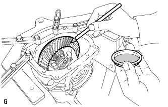
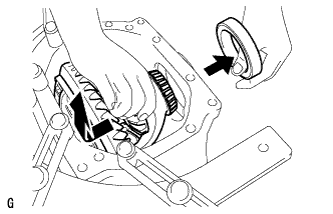
Uniformly apply a light coat of Prussian blue on both sides of 4 teeth on the differential ring gear.
-
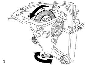
Rotate the companion flange several times in the forward and backward rotation directions.
-
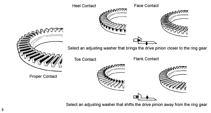
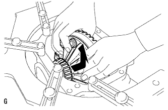
Inspect the tooth contact pattern.
Tech Tips
The patterns indicated by the Prussian blue are the tooth contact locations.
Note
Check the tooth contact pattern at 4 or more positions around the circumference of the ring gear.
-
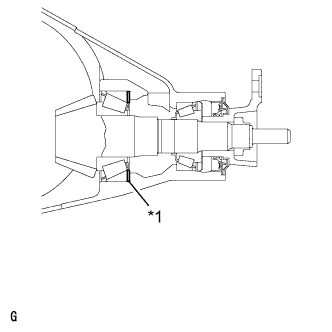
Text in Illustration *1 Differential Drive Pinion Washer If the teeth are not contacting properly, use the following table to select a proper drive pinion washer for correction.
Remove the rear drive pinion front tapered roller bearing outer race, following the procedures listed below and then replace the rear differential drive pinion washer with a proper one.
Note
Make sure to always replace the drive pinion washer with a new one.
Standard washer thickness Thickness mm (in.) No. Thickness mm (in.) No. Thickness mm (in.) No. 1.865 to 1.875 (0.0734 to 0.0738) 87 2.005 to 2.015 (0.0789 to 0.0793) 01 2.145 to 2.155 (0.0844 to 0.0848) 15 1.875 to 1.885 (0.0738 to 0.0742) 88 2.015 to 2.025 (0.0793 to 0.0797) 02 2.155 to 2.165 (0.0848 to 0.0852) 16 1.885 to 1.895 (0.0742 to 0.0746) 89 2.025 to 2.035 (0.0797 to 0.0801) 03 2.165 to 2.175 (0.0852 to 0.0856) 17 1.895 to 1.905 (0.0746 to 0.0750) 90 2.035 to 2.045 (0.0801 to 0.0805) 04 2.175 to 2.185 (0.0856 to 0.0860) 18 1.905 to 1.915 (0.0750 to 0.0754) 91 2.045 to 2.055 (0.0805 to 0.0809) 05 2.185 to 2.195 (0.0860 to 0.0864) 19 1.915 to 1.925 (0.0754 to 0.0758) 92 2.055 to 2.065 (0.0809 to 0.0813) 06 2.195 to 2.205 (0.0864 to 0.0868) 20 1.925 to 1.935 (0.0758 to 0.0762) 93 2.065 to 2.075 (0.0813 to 0.0817) 07 2.205 to 2.215 (0.0868 to 0.0872) 21 1.935 to 1.945 (0.0762 to 0.0766) 94 2.075 to 2.085 (0.0817 to 0.0821) 08 2.215 to 2.225 (0.0872 to 0.0876) 22 1.945 to 1.955 (0.0766 to 0.0770) 95 2.085 to 2.095 (0.0821 to 0.0825) 09 2.225 to 2.235 (0.0876 to 0.0880) 23 1.955 to 1.965 (0.0770 to 0.0774) 96 2.095 to 2.105 (0.0825 to 0.0829) 10 2.235 to 2.245 (0.0880 to 0.0884) 24 1.965 to 1.975 (0.0774 to 0.0778) 97 2.105 to 2.115 (0.0829 to 0.0833) 11 2.245 to 2.255 (0.0884 to 0.0888) 25 1.975 to 1.985 (0.0778 to 0.0781) 98 2.115 to 2.125 (0.0833 to 0.0837) 12 2.255 to 2.265 (0.0888 to 0.0892) 26 1.985 to 1.995 (0.0781 to 0.0785) 99 2.125 to 2.135 (0.0837 to 0.0841) 13 2.265 to 2.275 (0.0892 to 0.0896) 27 1.995 to 2.005 (0.0785 to 0.0789) 00 2.135 to 2.145 (0.0841 to 0.0844) 14 2.275 to 2.285 (0.0896 to 0.0900) 28
-
-
REMOVE REAR DIFFERENTIAL SIDE GEAR SHAFT SHAFT SNAP RING
-
Text in Illustration *1 Disc Install the 2 bolts and SST to the differential carrier.
- SST
- 09571-50010
-
Tighten SST bolt until SST disc lightly touches the case bearing outer race.
-
Install a dial indicator to the rear differential carrier.
-
Tighten SST bolt and alter the differential carrier's shape to create a 0.1 mm (0.00394 in.) clearance between the case bearing outer race and side gear shaft snap ring.
Note
Observe the dial indicator to ensure that the shape of the differential carrier does not change more than 0.2 mm (0.00787 in.).
Tech Tips
-
Try to set the dial indicator as close as possible to the differential carrier cover side (upper side in illustration) of the differential case bearing outer race.
-
The approximate 0.1 mm (0.00394 in.) clearance between the differential case bearing outer race and the differential side gear shaft snap ring only needs to be enough so that the differential side gear shaft snap ring can move slightly.
-
-
Using snap ring pliers, remove the side gear shaft snap ring on the ring gear tooth side.
Tech Tips
Place distinguishing marks on the left and right side differential side gear shaft snap rings to distinguish them (back surface side, tooth side). Then store them separately.
-
Remove the dial indicator from the differential carrier.
-
Text in Illustration *1 Disc *a Turn Loosen SST bolt until SST disc separates from the tooth side of the differential case bearing outer race.
Note
Do not remove SST.
-
-
REMOVE REAR DIFFERENTIAL SIDE GEAR SHAFT SHAFT SNAP RING
-
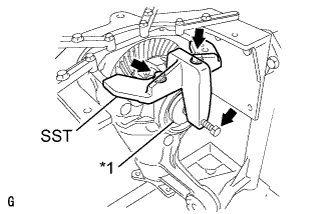
Using SST and a hammer, create a clearance between the case bearing outer race on the back surface of the ring gear and side gear shaft snap ring.
- SST
- 09608-32010
- 09950-70010 ( 09951-07200 )
Tech Tips
The clearance is not visible, but tapping SST with a hammer 3 or 4 times should be enough.
-
Using snap ring pliers, remove the side gear shaft snap ring on the back surface of the ring gear.
Tech Tips
Place distinguishing marks on the left and right side differential side gear shaft snap rings to distinguish them (back surface side, tooth side). Then store them separately.
-
-
REMOVE REAR DIFFERENTIAL CASE BEARING OUTER RACE
-
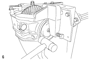
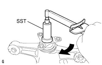
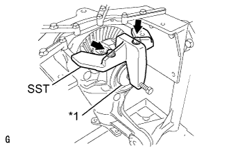
Text in Illustration *a Turn Tighten SST bolt and push out the case bearing outer race on the ring gear back surface side.
- SST
- 09571-50010
Note
Do not drop the case bearing outer race.
Tech Tips
-
For reassembly purposes, mark the installation positions of the differential case bearing outer race and differential side gear shaft snap ring.
-
Place distinguishing marks on the left and right side differential case bearing outer races to distinguish them (back surface side, tooth side). Then store them separately.
-
Remove the 2 bolts and SST from the differential carrier.
-
-
REMOVE REAR DIFFERENTIAL CASE BEARING OUTER RACE
-
Raise the ring gear of the differential case slightly and remove the ring gear tooth side case bearing outer race.
Note
Do not drop the case bearing outer race.
Tech Tips
-
For reassembly purposes, mark the installation positions of the differential case bearing outer race and differential side gear shaft snap ring.
-
Place distinguishing marks on the left and right side differential case bearing outer races to distinguish them (back surface side, tooth side). Then store them separately.
-
-
-
REMOVE REAR DIFFERENTIAL CASE SUB-ASSEMBLY
-
Pull out the differential case from the back surface side of the ring gear, and remove it from the differential carrier.
Note
Do not damage the case bearing and ring gear.
-
-
REMOVE REAR DRIVE PINION NUT
-
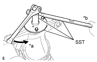
Text in Illustration *a Turn *b Hold Using SST, fix the companion flange in place.
- SST
- 09330-00021
- 09950-30012 ( 09955-03040 )
-
Using SST, remove the drive pinion nut from the differential carrier.
- SST
- 09229-55010
Tech Tips
Perform the removal while supporting the overhaul attachment.
-
-
REMOVE REAR DRIVE PINION COMPANION FLANGE REAR SUB-ASSEMBLY
-
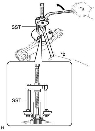
Text in Illustration *a Turn *b Hold Using SST, remove the companion flange from the differential carrier.
- SST
- 09950-30012 ( 09951-03010, 09953-03010, 09954-03010, 09955-03040, 09956-03060 )
Tech Tips
Before using SST center bolt, apply hypoid gear oil to its threads and tip.
-
-
REMOVE REAR DIFFERENTIAL DRIVE PINION OIL SLINGER
-
Remove the differential drive pinion oil slinger from the differential drive pinion.
-
-
REMOVE DIFFERENTIAL DRIVE PINION
-
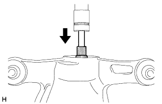
Using a press, press out the drive pinion from the differential carrier.
Note
Do not drop the drive pinion.
-
-
REMOVE REAR DRIVE PINION FRONT TAPERED ROLLER BEARING INNER RACE
-
Remove the rear drive pinion front tapered roller bearing from the differential carrier.
-
-
INSTALL REAR DIFFERENTIAL DRIVE PINION BEARING SPACER
-
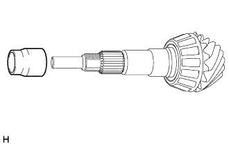
Install a new drive pinion bearing spacer to the drive pinion.
Tech Tips
The bearing spacer can be installed facing either direction.
-
-
INSTALL REAR DRIVE PINION FRONT TAPERED ROLLER BEARING INNER RACE
-
Install the rear drive pinion front tapered roller bearing inner race to the differential carrier.
-
-
INSTALL DIFFERENTIAL DRIVE PINION
-
Using SST and a press, press in the differential drive pinion to the differential carrier.
- SST
- 09316-60011 ( 09316-00011, 09316-00041 )
- 09608-04031
-
-
INSTALL REAR DIFFERENTIAL DRIVE PINION OIL SLINGER
-
Install the differential drive pinion oil slinger to the differential drive pinion.
-
-
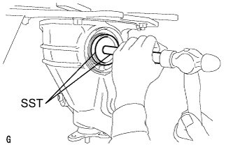
INSTALL REAR DIFFERENTIAL CARRIER OIL SEAL
-
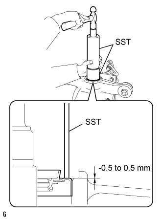
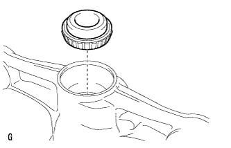
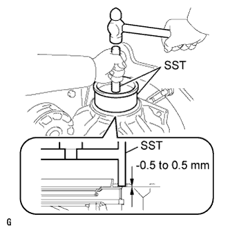
Using SST and a hammer, tap in a new oil seal.
- SST
- 09316-60011 ( 09316-00011 )
- 09710-04101
Note
-
Tap the oil seal uniformly so that the oil seal is straight.
-
Do not excessively tap the oil seal.
-
Using a vernier caliper, measure the depth of the oil seal.
Standard depth -0.5 to 0.5 mm (-0.0197 to 0.0196 in.) Note
-
Measure at 3 or more areas around the circumference of the oil seal.
-
Make sure the difference between the maximum and minimum measured values is less than 0.65 mm (0.0256 in.), as a greater difference may lead to oil leaks.
-
-
-
INSTALL REAR DRIVE PINION COMPANION FLANGE REAR SUB-ASSEMBLY
-
Text in Illustration *a Turn *b Hold Using SST, install the companion flange to the differential carrier.
- SST
- 09950-30012 ( 09951-03010, 09953-03010, 09954-03010, 09955-03040, 09956-03060 )
Note
Perform this procedure after aligning the companion flange with the spline of the drive pinion.
Tech Tips
Before using SST center bolt, apply hypoid gear oil to its threads and tip.
-
Coat the threads of a new drive pinion nut with hypoid gear oil LSD.
-
Text in Illustration *a Turn *b Hold Use SST to hold the companion flange.
- SST
- 09950-30012 ( 09955-03040 )
-
Using SST and a torque wrench, tighten the drive pinion nut while checking the starting torque of the drive pinion.
- SST
- 09229-55010
- 09330-00021
Maximum torque 490 N*m (5000 kgf*cm, 361 ft.*lbf) or less Note
-
Do not overtighten the nut, as the threads will become damaged.
-
Perform the tightening while supporting the overhaul attachment.
Tech Tips
-
Tighten the nut with a force of 100 N*m (1020 kgf*cm, 74 ft.*lbf) and keep tightening while checking the starting torque of the drive pinion.
-
Apply hypoid gear oil LSD to the threads of the nut and drive pinion.
-
-
INSTALL REAR DIFFERENTIAL CASE SUB-ASSEMBLY
-
Insert the differential case from the ring gear tooth side.
Note
Do not damage the case bearing inner race and ring gear.
-
-
INSTALL REAR DIFFERENTIAL CASE BEARING OUTER RACE
-
Text in Illustration *a Groove Using SST and a hammer, tap in the ring gear tooth side case bearing outer race.
- SST
- 09608-32010
- 09950-70010 ( 09951-07200 )
Tech Tips
Tap in the case bearing outer race until half of the side gear shaft snap ring groove of the differential carrier can be seen.
-
Text in Illustration *1 Disc Install SST to the differential carrier with the 2 bolts.
- SST
- 09571-50010
-
Tighten SST bolt until SST disc lightly touches the case bearing outer race.
-
Using SST and a hammer, tap in the ring gear back surface side case bearing outer race.
- SST
- 09608-32010
- 09950-70010 ( 09951-07200 )
Tech Tips
Tap in the case bearing outer race until it touches the case bearing inner race roller bearing.
-
-
INSTALL REAR DIFFERENTIAL SIDE GEAR SHAFT SHAFT SNAP RING
-
Using snap ring pliers, install the side gear shaft snap ring in the differential carrier on the ring gear back surface side.
Note
Check that the differential side gear shaft snap ring is securely fitted into the groove.
Tech Tips
Use the side gear shaft snap ring that was used during the tooth contact adjustment.
-
Install a dial indicator on the differential carrier.
-
Tighten SST bolt, and push in the differential case.
Tech Tips
-
Try to set the dial indicator as close as possible to the differential carrier cover side (upper side in illustration) of the differential case bearing outer race.
-
Approximate 0.1 mm (0.00394 in.) clearance between the differential case bearing outer race and the differential side gear shaft snap ring only needs to be enough so that the differential side gear shaft snap ring can move slightly.
Note
Observe the dial indicator to ensure that the shape of the differential carrier does not change more than 0.2 mm (0.00787 in.).
-
-
Remove the dial indicator and using snap ring pliers, install the side gear shaft snap ring on the ring gear tooth side.
Tech Tips
Use the side gear shaft snap ring that was used during the tooth contact adjustment.
-
Text in Illustration *1 Disc *a Turn Loosen SST bolt until SST disc separates from the tooth side of the differential case bearing outer race.
-
Tap the differential carrier on the ring gear tooth side using a plastic-faced hammer to stabilize the case bearing.
-
Remove the 2 bolts and SST from the differential carrier.
-
-
ADJUST DRIVE PINION PRELOAD
-
Using SST and a torque wrench, measure the preload.
- SST
- 09229-55010
Standard total preload (at starting) 1.25 to 1.65 N*m (13 to 16 kgf*cm, 11 to 14 in.*lbf) Tech Tips
-
For a more accurate measurement, rotate the flange forward and backward several times before the measurement.
-
Check the starting torque of the drive pinion for use with the total preload inspection.
Note
-
The bearing spacer is made of plastic and changes shape when used. If the starting torque of the drive pinion is exceeded by mistake, make sure to replace the bearing spacer with a new one.
-
If the starting torque of the drive pinion is exceeded, replace the bearing spacer.
-
If the starting torque of the drive pinion is insufficient, tighten the drive pinion nut 5 to 10° at a time.
Maximum torque 490 N*m (5000 kgf*cm, 361 ft.*lbf) or less Repeat the adjustment as necessary until the starting torque matches the specified torque.
-
If the tightening torque of the pinion nut exceeds the specified torque but the drive pinion starting torque is still insufficient, loosen the pinion nut. Then check if the pinion nut and drive pinion threads are damaged.
-
If there are no problems, replace the bearing spacer, apply hypoid gear oil LSD to its threads and repeat the procedure above.
-
-
INSPECT TOTAL PRELOAD
-
Using SST and a torque wrench, measure the preload with the teeth of the drive pinion and ring gear in contact.
- SST
- 09229-55010
Standard total preload New bearing 1.87 to 3.39 N*m (19 to 34 kgf*cm, 17 to 30 in.*lbf) Reused bearing 1.71 to 2.87 N*m (18 to 29 kgf*cm, 16 to 25 in.*lbf)
-
-
INSPECT DIFFERENTIAL RING GEAR BACKLASH
-
Place a dial indicator so that it is perpendicular to the top of the ring gear on the tooth side.
-
Fix the companion flange in place, and measure the ring gear backlash.
Standard backlash 0.08 to 0.13 mm (0.00315 to 0.00511 in.) Tech Tips
Measure at 3 or more areas around the circumference of the ring gear.
-
-
INSPECT RUNOUT OF DIFFERENTIAL DRIVE PINION
-
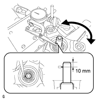
Using a dial indicator, measure the runout of the drive pinion shaft at a position 10 mm (0.394 in.) from the end of the shaft.
Maximum runout 0.08 mm (0.00315 in.)
-
-
STAKE REAR DRIVE PINION NUT
-
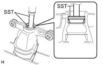
Using a SST and a hammer, stake the drive pinion nut.
- SST
- 09930-00010
-
-
INSTALL REAR DIFFERENTIAL SIDE GEAR SHAFT OIL SEAL
-
Using SST and a hammer, install 2 new oil seals.
- SST
- 09223-15030
- 09950-70010 ( 09951-07150 )
Standard depth -0.5 to 0.5 mm (-0.0197 to 0.0196 in.) Note
-
Tap the oil seal uniformly so that the oil seal is straight.
-
After the installation, check that the oil seal has been tapped securely onto the differential.
-
-
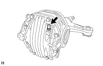
INSTALL REAR DIFFERENTIAL DRAIN PLUG
Tech Tips
Perform this procedure as necessary.
-
Using a 10 mm socket hexagon wrench, install a new gasket and drain plug to the rear differential carrier.
- Torque:
- 49 N*m { 500 kgf*cm, 36 ft.*lbf }
-
-
INSTALL REAR DIFFERENTIAL FILLER PLUG
Tech Tips
Perform this procedure as necessary.
-
Using a 10 mm socket hexagon wrench, install a new gasket and filler plug to the rear differential carrier.
- Torque:
- 49 N*m { 500 kgf*cm, 36 ft.*lbf }
-
-
REMOVE REAR DIFFERENTIAL CARRIER ASSEMBLY FROM OVERHAUL STAND
-
Remove the differential carrier from the overhaul stand.
-
-
INSTALL REAR DIFFERENTIAL BREATHER PLUG OIL DEFLECTOR
-
Remove the seal packing attached on the differential carrier and carrier cover using a scraper and wire brush. Then wipe off the oil with a non-residue solvent or equivalent.
Note
Do not scratch the fitting surface.
-
Install the rear differential breather plug oil deflector to the rear differential carrier cover with the bolt.
- Torque:
- 7.0 N*m { 71 kgf*cm, 62 in.*lbf }
-
-
INSTALL REAR DIFFERENTIAL CARRIER COVER
-
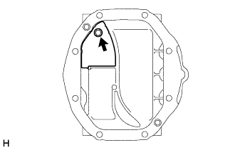
Text in Illustration *1 Seal Packing Apply seal packing to the differential carrier as shown in the illustration.
Seal packing Toyota Genuine Seal Packing 1281, Three bond 1281 or equivalent Note
-
Apply the seal packing in a continuous line, approximately 2 to 3 mm (0.0787 to 0.118 in.) in diameter.
-
Overlap the seal packing at least 10 mm (0.394 in.) at the beginning and the end of application.
-
Install the differential carrier cover within 3 minutes of application.
-
-
Install the differential carrier cover with the 8 bolts.
- Torque:
- 47 N*m { 479 kgf*cm, 35 ft.*lbf }
Note
Do not fill the oil or drive immediately after installing the differential carrier cover. Leave the vehicle for at least 1 hour. Also, avoid sudden acceleration and deceleration for at least 12 hours after application.
-
-
INSTALL REAR DIFFERENTIAL CARRIER COVER BREATHER PLUG
-
Install the breather plug to the differential carrier cover.
- Torque:
- 21 N*m { 214 kgf*cm, 16 ft.*lbf }
-