PROPELLER SHAFT ASSEMBLY INSTALLATION

-
INSTALL PROPELLER SHAFT WITH CENTER BEARING ASSEMBLY
-
Apply grease to the flexible coupling centering bushings.
Grease Molybdenum disulphide lithium base NLGI No. 2 -
Completely remove any oil or the like and clean the contact surfaces of the transmission companion flange and flexible coupling.
-
Completely remove any oil or the like and clean the contact surfaces of the differential companion flange and flexible coupling.
-
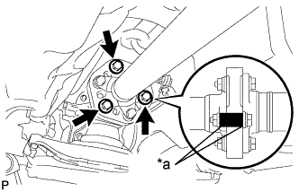
Text in Illustration *a Matchmark Align the matchmarks on the transmission companion flange and flexible coupling.
-
Install and tighten the 3 bolts. 3 washers and 3 nuts.
- Torque:
- 79 N*m { 806 kgf*cm, 58 ft.*lbf }
Tech Tips
The bolts should be installed from the propeller shaft side.
Note
Be careful not to damage the flexible coupling centering bush.
-
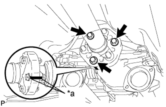
Text in Illustration *a Matchmark Align the matchmarks on the differential companion flange and flexible coupling.
-
Install the 3 bolts, 3 washers and 3 nuts.
- Torque:
- 79 N*m { 806 kgf*cm, 58 ft.*lbf }
Tech Tips
The bolts should be installed from the propeller shaft side.
Note
Be careful not to damage the flexible coupling centering bush.
-
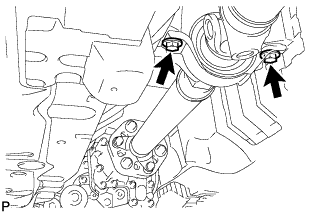
Temporarily install the 2 bolts with the adjusting washers.
Tech Tips
Use the adjusting washers which were removed.
-
-
TIGHTEN NO. 1 CENTER SUPPORT BEARING ASSEMBLY
-
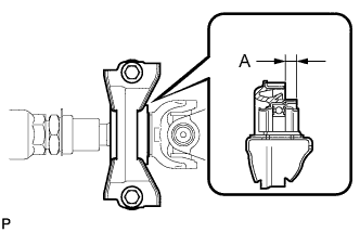
Adjust the distance (A) between the surface of the center support bearing and the surface of the cushion to 11.5 to 13.5 mm (0.453 to 0.531 in.) as shown in illustration.
Distance (A) 11.5 to 13.5 mm (0.453 to 0.531 in.) -
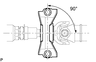
Check that the center line of the bracket is at a right angle to the shaft axial direction.
-
Tighten the 2 bolts.
- Torque:
- 49 N*m { 501 kgf*cm, 36 ft.*lbf }
-
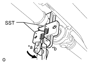
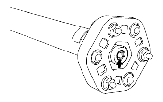
Text in Illustration *a Turn *b Hold Using SST, tighten the adjusting nut.
- SST
- 09922-10010
- Torque:
- without SST
- 69 N*m { 704 kgf*cm, 51 ft.*lbf }
- with SST
- 51 N*m { 520 kgf*cm, 38 ft.*lbf }
Tech Tips
-
Use a torque wrench with a fulcrum length of 34.5 cm (1.13 ft.).
-
Make sure SST and wrench are connected in a straight line.
-
-
INSPECT AND ADJUST NO. 2 AND NO. 3 JOINT ANGLE
-
Stabilize the propeller shaft and differential.
-
Turn the propeller shaft several times by hand to stabilize the center support bearing.
-
-
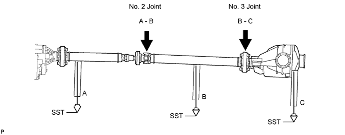
Check the No. 2 and No. 3 joint angles.
-
Using SST, measure the installation angle of the intermediate shaft and propeller shaft.
- SST
- 09370-50010
Tech Tips
SST should be set directly underneath the shaft.
-
Using SST, measure the installation angle of the differential.
- SST
- 09370-50010
Tech Tips
Measure the installation angle by placing SST in the positions shown in the illustration.
-
Calculate the No. 2 joint angle.
Standard No. 2 joint angle Vehicle Model A - B for Standard Body -0°23' to 0°31' for Long Body -0°25' to 0°29' Tech Tips
A = Intermediate shaft installation angle
B = Propeller shaft installation angle
-
Calculate the No. 3 joint angle.
Standard No. 3 joint angle Vehicle Model B - C for Standard Body 1°05' to 1°59' for Long Body 0°55' to 1°49' Tech Tips
B = Propeller shaft installation angle
C = Differential installation angle
If the measured angle is not within the specified range, adjust it with the center support bearing washers.
-
-
Adjust the No. 2 joint angle.
-
Select an appropriate center support bearing washer thickness from the table below, and obtain a washer set.
Standard adjustment washer Thickness 2.0 mm (0.0787 in.) 4.5 mm (0.1772 in.) 6.5 mm (0.2559 in.) 9.0 mm (0.3543 in.) 11.0 mm (0.4331 in.) Note
-
Each set contains 2 washers.
-
Using the washer set, perform the adjustment.
-
-
-
-
INSTALL PROPELLER SHAFT HEAT INSULATOR
-
Install the propeller shaft heat insulator with the 2 bolts.
- Torque:
- 5.4 N*m { 55 kgf*cm, 48 in.*lbf }
-
-
INSTALL FRONT FLOOR NO. 1 HEAT INSULATOR
-
Install the heat insulator with the 6 nuts.
- Torque:
- 5.4 N*m { 55 kgf*cm, 48 in.*lbf }
-
-
INSTALL FRONT EXHAUST PIPE ASSEMBLY
-
INSPECT FOR EXHAUST GAS LEAK
-
If gas is leaking, tighten the areas necessary to stop the leak. Replace the damaged parts as necessary.
-