TRANSFER ASSEMBLY REASSEMBLY

-
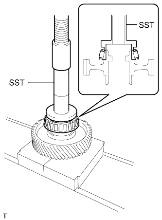
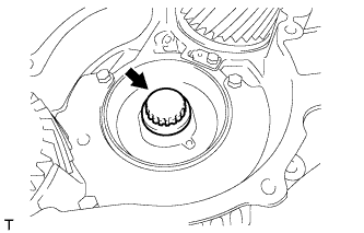
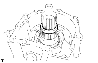
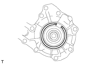
INSTALL TRANSFER FRONT DRIVE GEAR CYLINDRICAL ROLLER BEARING (for Rear Transfer Case Side)
-
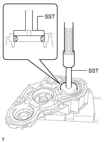
Using SST and a press, install a new bearing to the rear transfer case.
- SST
- 09950-60020 ( 09951-00710 )
- 09950-70010 ( 09951-07100 )
-
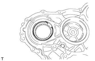
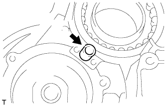
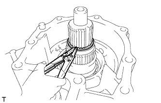
Using needle-nose pliers, install the snap ring to the rear transfer case.
-
-
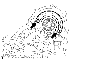
INSTALL TRANSFER FRONT DRIVE GEAR BEARING
-
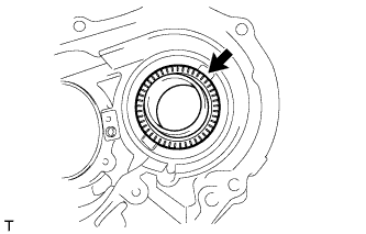
Install the bearing and bearing race to the front transfer case.
-
-
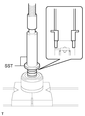
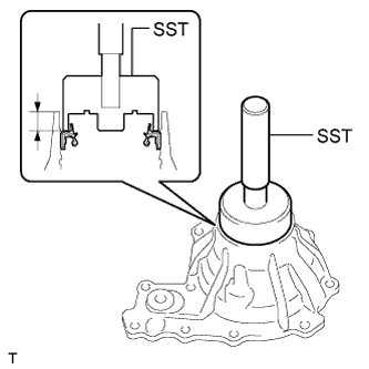
INSTALL TRANSFER FRONT DRIVE GEAR CYLINDRICAL ROLLER BEARING (for Front Transfer Case Side)
-
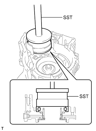
Using SST and a press, install a new bearing (outer race) to the front transfer case.
- SST
- 09527-17011
- 09951-01000
- 09950-70010 ( 09951-07150 )
-
-
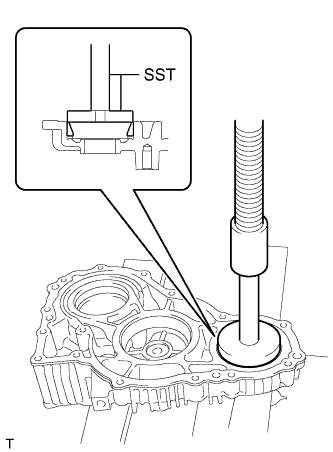
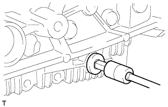
INSTALL TRANSFER FRONT CASE OIL SEAL
-
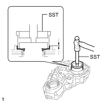
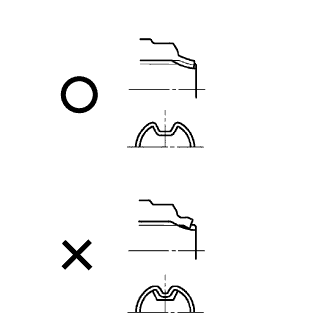
Using SST and a hammer, install a new oil seal to the front transfer case.
- SST
- 09223-15020
Standard depth 1.0 to 1.5 mm (0.0394 to 0.0591 in.) Note
-
Do not tap in the oil seal at an angle.
-
Do not tap in the oil seal excessively.
-
Coat the lip of the outer shaft lever oil seal with MP grease.
-
-
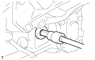
INSTALL TRANSFER OUTPUT SHAFT COMPANION FLANGE OIL SEAL
-
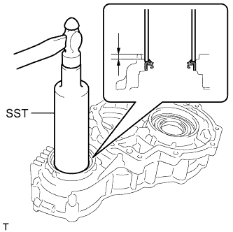
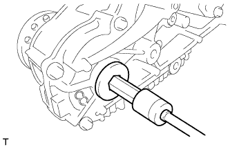
Using SST and a hammer, install a new oil seal to the front transfer case.
- SST
- 09316-60011 ( 09316-00011 )
Standard depth 2.5 to 3.0 mm (0.0984 to 0.118 in.) Note
-
Do not tap in the oil seal at an angle.
-
Do not tap in the oil seal excessively.
-
Coat the lip of the outer shaft lever oil seal with MP grease.
-
-
INSTALL FORWARD CLUTCH DRAM OIL SEAL RING
-
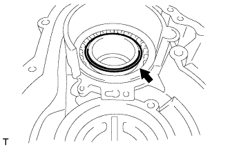
Install the oil seal ring to the sleeve.
-
-
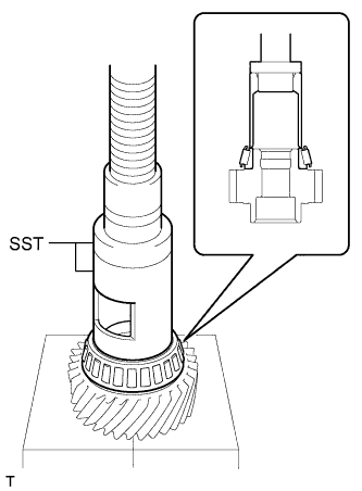
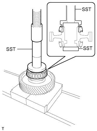
INSTALL TRANSFER COUNTER GEAR BEARING (for Front Transfer Case Side)
-
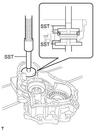
Using SST and a press, install a new bearing (outer race) to the front transfer case.
- SST
- 09950-60010 ( 09951-00580, 09951-00630, 09952-06010 )
- 09950-60020 ( 09951-00750, 09951-00790, 09952-06010 )
- 09950-70010 ( 09951-07100 )
-
-
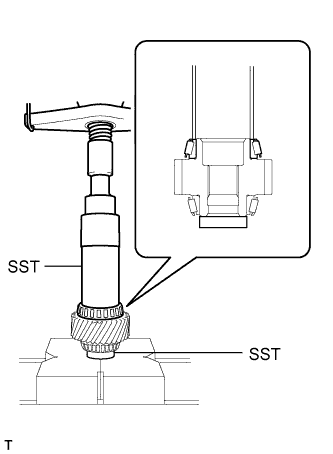
INSTALL TRANSFER COUNTER GEAR BEARING
-
for Front Transfer Case Side:
-
Using SST and a press, install a new bearing (inner race) to the counter gear.
- SST
- 09316-60011 ( 09316-00011, 09613-22011 )
- 09950-60010 ( 09951-00420 )
Tech Tips
Disassemble SST (09613-22011) and only use the tube part.
-
-
for Rear Transfer Case Side:
-
Using SST and a press, install a new bearing (inner race) to the counter gear.
- SST
- 09316-60011 ( 09316-00011 )
- 09950-60010 ( 09951-00420 )
-
-
-
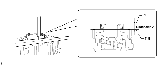
ADJUST COUNTER GEAR BEARING PRELOAD
-
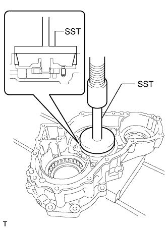
Using a vernier caliper and precision straightedge, measure dimension A between the top surface of the front transfer case [*1] and the top surface of the counter gear bearing (outer race) [*2].
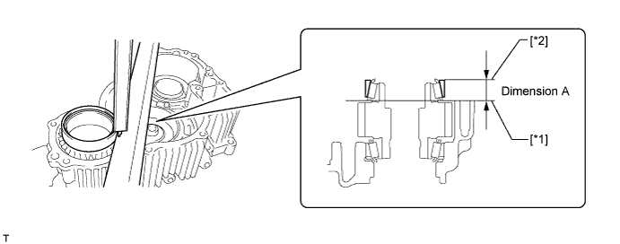
Tech Tips
Perform the measurement at 3 locations at intervals of 120° around the circumference of the outer race and calculate the average.
Note
Perform the measurements with the idler gear assembly removed.
-
Using a vernier caliper and precision straightedge, measure dimension B between the top surface of the rear transfer case [*1] and the surface which contacts the transfer counter gear shim [*2].
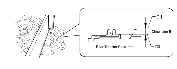
Note
Do not add the thickness of the precision straightedge.
-
Using the formula below, calculate the thickness of the transfer counter gear shim and select an appropriate shim from the table.
Transfer counter gear shim thickness Dimension B - Dimension A Transfer Counter Gear Shim Thickness Mark Specified Condition Mark Specified Condition Mark Specified Condition 40 1.39 to 1.41 mm (0.0548 to 0.0555 in) 72 1.71 to 1.73 mm (0.0673 to 0.0681 in) 04 2.03 to 2.05 mm (0.0799 to 0.0807 in) 42 1.41 to 1.43 mm (0.0555 to 0.0562 in) 74 1.73 to 1.75 mm (0.0681 to 0.0688 in) 06 2.05 to 2.07 mm (0.0807 to 0.0814 in) 44 1.43 to 1.45 mm (0.0562 to 0.0570 in) 76 1.75 to 1.77 mm (0.0688 to 0.0696 in) 08 2.07 to 2.09 mm (0.0814 to 0.0822 in) 46 1.45 to 1.47 mm (0.0570 to 0.0578 in) 78 1.77 to 1.79 mm (0.0696 to 0.0704 in) 10 2.09 to 2.11 mm (0.0822 to 0.0830 in) 48 1.47 to 1.49 mm (0.0578 to 0.0586 in) 80 1.79 to 1.81 mm (0.0704 to 0.0712 in) 12 2.11 to 2.13 mm (0.0830 to 0.0838 in) 50 1.49 to 1.51 mm (0.0586 to 0.0594 in) 82 1.81 to 1.83 mm (0.0712 to 0.0720 in) 14 2.13 to 2.15 mm (0.0838 to 0.0846 in) 52 1.51 to 1.53 mm (0.0594 to 0.0602 in) 84 1.83 to 1.85 mm (0.0720 to 0.0728 in) 16 2.15 to 2.17 mm (0.0846 to 0.0854 in) 54 1.53 to 1.55 mm (0.0602 to 0.0610 in) 86 1.85 to 1.87 mm (0.0728 to 0.0736 in) 18 2.17 to 2.19 mm (0.0854 to 0.0862 in) 56 1.55 to 1.57 mm (0.0610 to 0.0618 in) 88 1.87 to 1.89 mm (0.0736 to 0.0744 in) 20 2.19 to 2.21 mm (0.0862 to 0.0870 in) 58 1.57 to 1.59 mm (0.0618 to 0.0625 in) 90 1.89 to 1.91 mm (0.0744 to 0.0751 in) 22 2.21 to 2.23 mm (0.0870 to 0.0877 in) 60 1.59 to 1.61 mm (0.0625 to 0.0633 in) 92 1.91 to 1.93 mm (0.0751 to 0.0759 in) 24 2.23 to 2.25 mm (0.0877 to 0.0885 in) 62 1.61 to 1.63 mm (0.0633 to 0.0641 in) 94 1.93 to 1.95 mm (0.0759 to 0.0767 in) 26 2.25 to 2.27 mm (0.0885 to 0.0893 in) 64 1.63 to 1.65 mm (0.0641 to 0.0649 in) 96 1.95 to 1.97 mm (0.0767 to 0.0775 in) 28 2.27 to 2.29 mm (0.0893 to 0.0901 in) 66 1.65 to 1.67 mm (0.0649 to 0.0657 in) 98 1.97 to 1.99 mm (0.0775 to 0.0783 in) 30 2.29 to 2.31 mm (0.0901 to 0.0909 in) 68 1.67 to 1.69 mm (0.0657 to 0.0665 in) 00 1.99 to 2.01 mm (0.0783 to 0.0791 in) - - 70 1.69 to 1.71 mm (0.0665 to 0.0673 in) 02 2.01 to 2.03 mm (0.0791 to 0.0799 in) - - -
Using SST and a press, install the shim and a new bearing (outer race) to the rear transfer case.
- SST
- 09950-60020 ( 09951-00750 )
- 09950-70010 ( 09951-07100 )
-
Install the counter gear to the front transfer case.
-
Install the rear transfer case with the 7 bolts to the front transfer case.
- Torque:
- 27 N*m { 275 kgf*cm, 20 ft.*lbf }
-
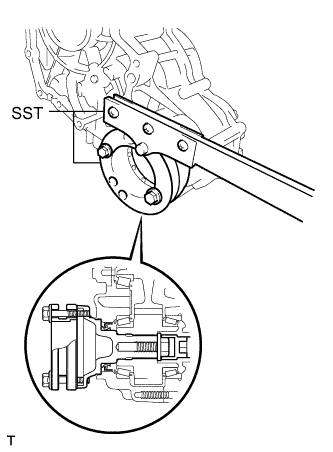
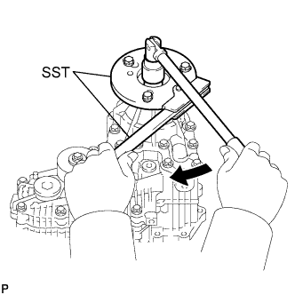
Install the companion flange to the transfer assembly, and then using SST, hold the companion flange in place.
- SST
- 09213-58013
- 09330-00021
Tech Tips
Use bolts of size M8 x P1.25 with a length of approximately 55 mm (2.16 in.) or equivalent to secure the companion flange.
-
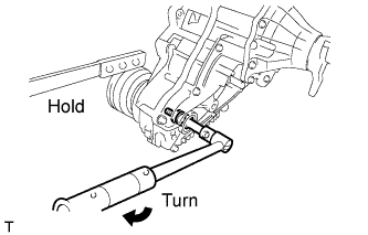
Tighten the companion flange bolt.
- Torque:
- 85 N*m { 867 kgf*cm, 63 ft.*lbf }
-
Remove SST and turn the counter gear back and forth to settle the bearing.
-
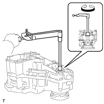
Using a torque wrench, measure the turning torque of the counter gear bearing (counter gear preload).
Standard turning torque 0.66 to 1.18 N*m (6.7 to 12.0 kgf*cm, 5.8 to 10.4 in.*lbf) Note
Perform the measurements with the idler gear assembly removed.
Tech Tips
Measure the turning torque while turning the counter gear at 60 rpm (1 rotation per second).
-
If the turning torque is not as specified, replace the counter gear shim with one of a different thickness so that the measured value is within the standard range.
-
-
Using SST, hold the companion flange in place.
- SST
- 09213-58013
- 09330-00021
Tech Tips
Use bolts of size M8 x P1.25 with a length of approximately 55 mm (2.16 in.) or equivalent to secure the companion flange.
-
Remove the companion flange bolt and companion flange from the transfer assembly.
-
Remove the 7 bolts from the rear transfer case.
-
Remove the counter gear.
-
-
INSTALL TRANSFER OIL PUMP PLATE SUB-ASSEMBLY
-
Install the drive rotor and driven rotor to the front transfer case.
-
Install the plate pin to the oil pump plate.
-
Install the plate to the front transfer case.
-
-
INSTALL TRANSFER IDLER GEAR BEARING (for Front Transfer Case Side)
-
Using SST and a press, install a new bearing (outer race) to the front transfer case.
- SST
- 09950-60020 ( 09951-00890 )
- 09950-70010 ( 09951-07100 )
-
-
INSTALL TRANSFER IDLER GEAR BEARING
-
for Front Transfer Case Side:
Using SST and a press, install a new bearing (inner race) to the idler gear.
- SST
- 09554-22010
-
for Rear Transfer Case Side:
Using SST and a press, install a new bearing (inner race) to the idler gear.
- SST
- 09950-60010 ( 09951-00540 )
- 09554-22010
-
-
ADJUST TRANSFER IDLER GEAR BEARING PRELOAD
-
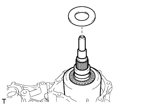
Install the counter gear to the front transfer case.
-
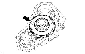
Install the idler gear to the front transfer case.
-
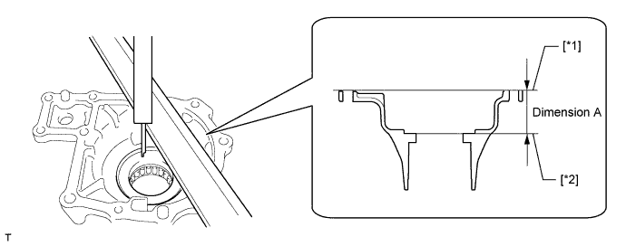
Using a vernier caliper and precision straightedge, measure dimension A between the top surface of the front transfer case [*1] and the top surface of the idler gear bearing (outer race) [*2].
Tech Tips
Perform the measurement at 3 locations at intervals of 120° around the circumference of the outer race and calculate the average.
-
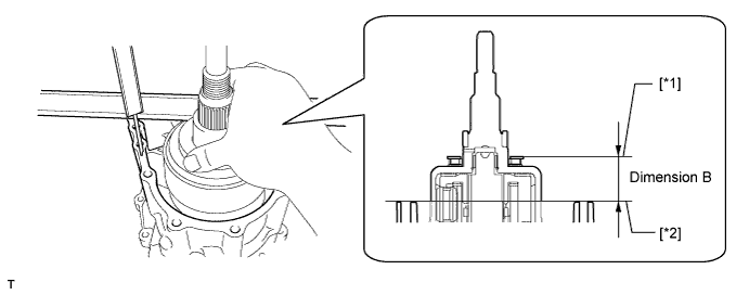
Using a vernier caliper and precision straightedge, measure dimension B between the top surface of the rear transfer case [*1] and the surface which contacts the transfer idler gear shim [*2].
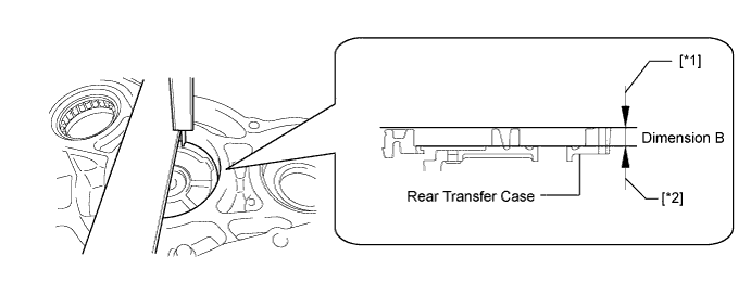
Note
Do not add the thickness of the precision straightedge.
-
Using the formula below, calculate the thickness of the transfer idler gear shim and select an appropriate shim from the table.
Transfer idler gear shim thickness Dimension B - Dimension A Transfer Idler Gear Shim Thickness Mark Specified Condition Mark Specified Condition Mark Specified Condition 90 0.89 to 0.91 mm (0.0350 to 0.0358 in) 22 1.21 to 1.23 mm (0.0476 to 0.0484 in) 54 1.53 to 1.55 mm (0.0602 to 0.0610 in) 92 0.91 to 0.93 mm (0.0358 to 0.0366 in) 24 1.23 to 1.25 mm (0.0484 to 0.0492 in) 56 1.55 to 1.57 mm (0.0610 to 0.0618 in) 94 0.93 to 0.95 mm (0.0366 to 0.0374 in) 26 1.25 to 1.27 mm (0.0492 to 0.0499 in) 58 1.57 to 1.59 mm (0.0618 to 0.0625 in) 96 0.95 to 0.97 mm (0.0374 to 0.0381 in) 28 1.27 to 1.29 mm (0.0499 to 0.0507 in) 60 1.59 to 1.61 mm (0.0625 to 0.0633 in) 98 0.97 to 0.99 mm (0.0381 to 0.0389 in) 30 1.29 to 1.31 mm (0.0507 to 0.0515 in) 62 1.61 to 1.63 mm (0.0633 to 0.0641 in) 00 0.99 to 1.01 mm (0.0389 to 0.0397 in) 32 1.31 to 1.33 mm (0.0515 to 0.0523 in) 64 1.63 to 1.65 mm (0.0641 to 0.0649 in) 02 1.01 to 1.03 mm (0.0397 to 0.0405 in) 34 1.33 to 1.35 mm (0.0523 to 0.0531 in) 66 1.65 to 1.67 mm (0.0649 to 0.0657 in) 04 1.03 to 1.05 mm (0.0405 to 0.0413 in) 36 1.35 to 1.37 mm (0.0531 to 0.0539 in) 68 1.67 to 1.69 mm (0.0657 to 0.0665 in) 06 1.05 to 1.07 mm (0.0413 to 0.0421 in) 38 1.37 to 1.39 mm (0.0539 to 0.0547 in) 70 1.69 to 1.71 mm (0.0665 to 0.0673 in) 08 1.07 to 1.09 mm (0.0421 to 0.0429 in) 40 1.39 to 1.41 mm (0.0547 to 0.0555 in) 72 1.71 to 1.73 mm (0.0673 to 0.0681 in) 10 1.09 to 1.11 mm (0.0429 to 0.0437 in) 42 1.41 to 1.43 mm (0.0555 to 0.0562 in) 74 1.73 to 1.75 mm (0.0681 to 0.0688 in) 12 1.11 to 1.13 mm (0.0437 to 0.0444 in) 44 1.43 to 1.45 mm (0.0562 to 0.0570 in) 76 1.75 to 1.77 mm (0.0688 to 0.0696 in) 14 1.13 to 1.15 mm (0.0444 to 0.0452 in) 46 1.45 to 1.47 mm (0.0570 to 0.0578 in) 78 1.77 to 1.79 mm (0.0696 to 0.0704 in) 16 1.15 to 1.17 mm (0.0452 to 0.0460 in) 48 1.47 to 1.49 mm (0.0578 to 0.0586 in) 80 1.79 to 1.81 mm (0.0704 to 0.0712 in) 18 1.17 to 1.19 mm (0.0460 to 0.0468 in) 50 1.49 to 1.51 mm (0.0586 to 0.0594 in) - - 20 1.19 to 1.21 mm (0.0468 to 0.0476 in) 52 1.51 to 1.53 mm (0.0594 to 0.0602 in) - - -
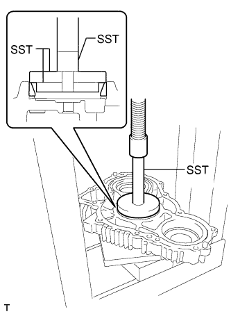
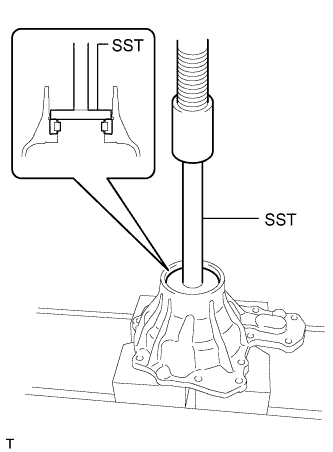
Using SST and a press, install the shim and a new bearing (outer race) to the rear transfer case.
- SST
- 09950-60020 ( 09951-00780, 09951-00890, 09952-06010 )
- 09950-70010 ( 09951-07100 )
-
Install the rear transfer case with the 7 bolts to the front transfer case.
- Torque:
- 27 N*m { 275 kgf*cm, 20 ft.*lbf }
-
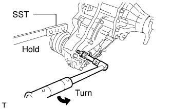
Install the companion flange to the transfer assembly, and then using SST, hold the companion flange in place.
- SST
- 09213-58013
- 09330-00021
Tech Tips
Use bolts of size M8 x P1.25 with a length of approximately 55 mm (2.16 in.) or equivalent to secure the companion flange.
-
Tighten the companion flange bolt.
- Torque:
- 85 N*m { 867 kgf*cm, 63 ft.*lbf }
-
Remove SST and turn the idler gear back and forth to settle the bearing.
-
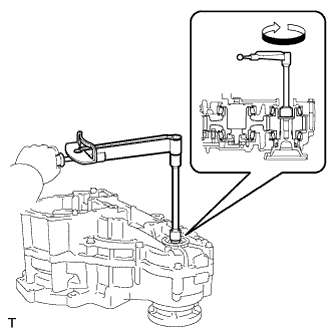
Using a torque wrench, measure the turning torque of the idler gear bearing (idler gear preload).
Standard turning torque 1.54 to 2.64 N*m (15.7 to 26.9 kgf*cm, 13.6 to 23.4 in.*lbf) Note
The measured turning torque for the idler gear preload is the combined preload of the idler gear and counter gear.
Tech Tips
Measure the turning torque while turning the counter gear at 60 rpm (1 rotation per second).
-
If the turning torque is not as specified, replace the idler gear shim with one of a different thickness so that the measured value is within the standard range.
-
-
Using SST, hold the companion flange in place.
- SST
- 09213-58013
- 09330-00021
Tech Tips
Use bolts of size M8 x P1.25 with a length of approximately 55 mm (2.16 in.) or equivalent to secure the companion flange.
-
Remove the companion flange bolt and companion flange form the transfer assembly.
-
Remove the 7 bolts and rear transfer case from the front transfer case.
-
Remove the idler gear and counter gear from the front transfer case.
-
-
INSTALL TRANSFER OIL COOLER RELIEF VALVE
-
Install the relief valve to the front transfer case.
-
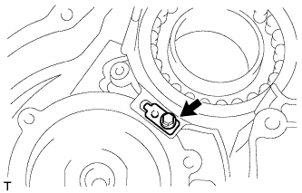
Install the compression spring and valve plate to the front transfer case with the bolt.
- Torque:
- 6.7 N*m { 68 kgf*cm, 59 in.*lbf }
Note
Be careful to prevent the relief valve compression spring from jumping out.
-
-
INSTALL NO. 1 TRANSFER OIL STRAINER
-
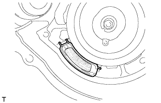
Install the oil strainer to the front transfer case.
-
-
INSTALL TRANSFER OIL SEPARATOR
-
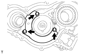
Install the oil separator with the 3 bolts.
- Torque:
- 7.0 N*m { 71 kgf*cm, 62 in.*lbf }
-
-
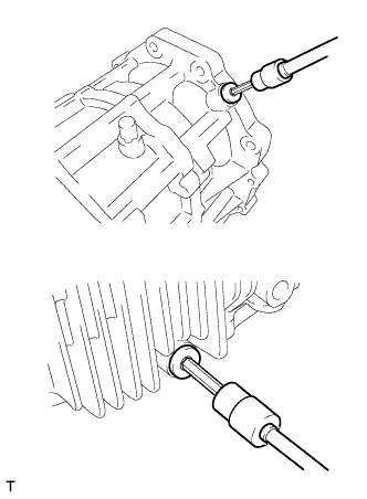
INSTALL DRIVE PINION COMPANION FLANGE OIL SEAL
-
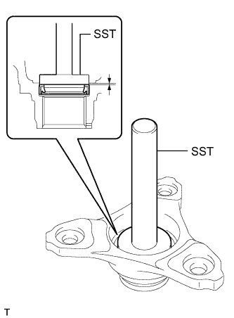
Using SST and a hammer, install a new oil seal to the companion flange.
- SST
- 09950-60010 ( 09951-00420 )
- 09950-70010 ( 09951-07100 )
Standard oil seal depth 0 to 0.3 mm (0 to 0.0118 in.) Note
-
Do not tap in the oil seal at an angle.
-
Do not tap in the oil seal excessively.
-
Coat the lip of the outer shaft lever oil seal with MP grease.
-
-
INSTALL TRANSFER OIL SEAL RING
-
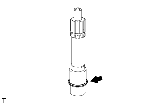
Install the oil seal ring to the input shaft.
Note
Do not excessively widen the oil seal ring.
-
-
INSTALL TRANSFER INPUT SHAFT
-
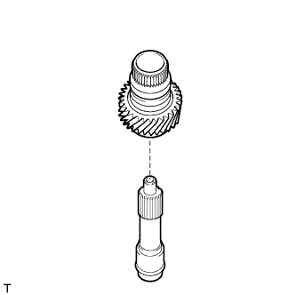
Install the input shaft to the drive gear.
-
-
INSTALL TRANSFER FRONT DRIVE GEAR PIN
-
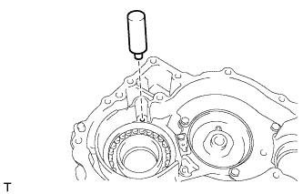
Install the pin to the front transfer case.
-
-
INSTALL TRANSFER FRONT DRIVE GEAR ASSEMBLY
-
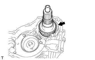
Install the drive gear and input shaft to the front transfer case.
-
-
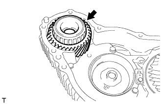
INSTALL TRANSFER COUNTER GEAR ASSEMBLY
-
Install the counter gear to the front transfer case.
-
-
INSTALL TRANSFER OIL PUMP DRIVE SHAFT
-
Install the drive shaft to the front transfer case.
-
-
INSTALL TRANSFER IDLER GEAR ASSEMBLY
-
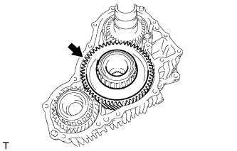
Install the idler gear to the front transfer case.
-
-
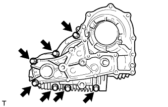
INSTALL REAR TRANSFER CASE
-
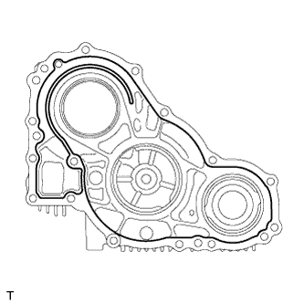
Apply seal packing to the rear transfer case as shown in the illustration.
Seal packing Toyota Genuine Seal Packing 1281, Three Bond 1281 or equivalent Seal packing diameter 1.2 mm (0.0472 in.) Note
-
Remove any oil from the contact surfaces.
-
Assemble the parts within 10 minutes of application. Otherwise, the packing (FIPG material) must be removed and reapplied.
-
-
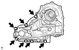
Install the rear transfer case with the 7 bolts to the front transfer case.
- Torque:
- 27 N*m { 275 kgf*cm, 20 ft.*lbf }
-
-
INSTALL TRANSFER INPUT GEAR STOPPER
-
Install the gear stopper to the input shaft.
-
-
INSTALL TRANSFER INPUT GEAR STOPPER SHAFT SNAP RING
-
Using a snap ring expander, install the snap ring to the input shaft.
-
-
INSTALL BREATHER OIL DEFLECTOR
-
Install the oil deflector with the 2 bolts to the rear transfer case.
- Torque:
- 7.0 N*m { 71 kgf*cm, 62 in.*lbf }
-
-
INSTALL TRANSFER OUTPUT SHAFT CYLINDRICAL ROLLER BEARING
-
Using SST and a press, install a new bearing (inner race) to the differential case.
- SST
- 09316-60011 ( 09316-00011, 09316-00021 )
-
-
INSTALL NO. 1 DIFFERENTIAL CASE SUB-ASSEMBLY
-
Install the differential case to the rear transfer case.
-
-
INSTALL TRANSFER OUTPUT SHAFT SHIM
-
Install the output shaft shim to the differential case.
-
-
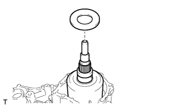
INSTALL NO. 2 TRANSFER THRUST BEARING RACE
-
Install the bearing race to the output shaft shim.
-
-
INSTALL DIFFERENTIAL CASE NEEDLE ROLLER BEARING
-
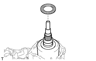
Install the needle roller bearing to the bearing race.
-
-
INSTALL TRANSFER OUTPUT SHAFT WASHER
-
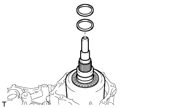
Install the 2 shaft washers to the differential case.
-
-
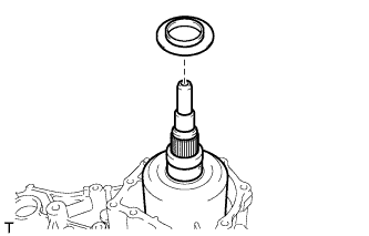
INSTALL NO. 1 TRANSFER THRUST BEARING RACE
-
Install the bearing race to the needle roller bearing.
-
-
ADJUST TRANSFER OUTPUT SHAFT SHIM
-
Using a vernier caliper and precision straightedge, measure dimension A between the top surface of the extension housing [*1] and the surface which contacts the No. 1 thrust bearing race [*2].
Note
Do not add the thickness of the precision straightedge.
-
Using a vernier caliper and precision straightedge, measure dimension B between the surface of the No. 1 thrust bearing race [*1] and the surface of the rear transfer case extension housing [*2].
Note
Do not add the thickness of the precision straightedge.
-
Using the formula below, calculate the thickness of the transfer output shim and select an appropriate shim from the table.
Transfer output shim thickness Dimension A - Dimension B Transfer Output Shim Thickness Mark Specified Condition Mark Specified Condition 98 0.96 to 1.00 mm (0.0378 to 0.0393 in.) 43 1.41 to 1.45 mm (0.0556 to 0.0570 in.) 03 1.01 to 1.05 mm (0.0398 to 0.0413 in.) 48 1.46 to 1.50 mm (0.0575 to 0.0590 in.) 08 1.06 to 1.10 mm (0.0418 to 0.0433 in.) 53 1.51 to 1.55 mm (0.0959 to 0.0610 in.) 13 1.11 to 1.15 mm (0.0437 to 0.0452 in.) 58 1.56 to 1.60 mm (0.0615 to 0.0629 in.) 18 1.16 to 1.20 mm (0.0457 to 0.0472 in.) 63 1.61 to 1.65 mm (0.0634 to 0.0649 in.) 23 1.21 to 1.25 mm (0.0477 to 0.0492 in.) 68 1.66 to 1.70 mm (0.0653 to 0.0669 in) 28 1.26 to 1.30 mm (0.0496 to 0.0511 in.) 73 1.71 to 1.75 mm (0.0674 to 0.0688 in.) 33 1.31 to 1.35 mm (0.0516 to 0.0532 in.) 78 1.76 to 1.80 mm (0.0693 to 0.0708 in.) 38 1.36 to 1.40 mm (0.0536 to 0.0551 in.) - -
-
-
INSTALL TRANSFER OUTPUT SHAFT CYLINDRICAL ROLLER BEARING
-
Using SST and a press, install a new bearing (outer race) to the extension housing.
- SST
- 09950-60010 ( 09951-00600 )
- 09950-70010 ( 09951-07100 )
-
-
INSTALL NO. 1 DIFFERENTIAL CASE HOLE SNAP RING
-
Using needle-nose pliers, install the snap ring to the extension housing.
-
-
INSTALL TRANSFER EXTENSION HOUSING OIL SEAL
-
Using SST and a hammer, install a new oil seal to the extension housing.
- SST
- 09726-36010
- 09950-70010 ( 09951-07100 )
Standard oil seal depth 12 to 12.5 mm (0.473 to 0.492 in.) Note
-
Do not tap in the oil seal at an angle.
-
Do not tap in the oil seal excessively.
-
Be careful of the positions of the straight pins when performing this procedure.
-
Coat the lip of the outer shaft lever oil seal with MP grease.
-
-
INSTALL TRANSFER EXTENSION HOUSING
-
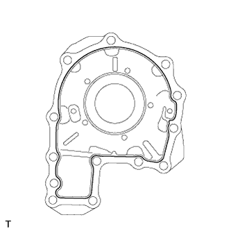
Apply seal packing to the transfer extension housing as shown in the illustration.
Seal packing Toyota Genuine Seal Packing 1281, Three Bond 1281 or equivalent Seal packing diameter 1.2 mm (0.0472 in.) Note
-
Remove any oil from the contact surfaces.
-
Assemble the parts within 10 minutes of application. Otherwise, the packing (FIPG material) must be removed and reapplied.
-
-
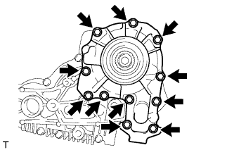
Install the transfer extension housing with the 11 bolts to the rear transfer case.
- Torque:
- 27 N*m { 275 kgf*cm, 20 ft.*lbf }
-
-
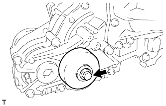
INSTALL DRIVE PINION COMPANION FLANGE SUB-ASSEMBLY
-
Install the companion flange to the output shaft.
-
Install a new nut to the output shaft.
-
Using SST, hold the companion flange in place.
- SST
- 09330-00021
- 09950-30012 ( 09955-03040 )
-
Using a 30 mm socket wrench, tighten the transfer output shaft nut.
- Torque:
- 142 N*m { 1448 kgf*cm, 105 ft.*lbf }
-
Using a chisel and hammer, stake the transfer output shaft nut.
-
-
INSTALL OUTPUT SHAFT COMPANION FLANGE SUB-ASSEMBLY
-
Install the companion flange to the transfer assembly, and then using SST, hold the companion flange in place.
- SST
- 09213-58013
- 09330-00021
Tech Tips
Use bolts of size M8 x P1.25 with a length of approximately 55 mm (2.16 in.) or equivalent to secure the companion flange.
-
Tighten the companion flange bolt.
- Torque:
- 85 N*m { 867 kgf*cm, 63 ft.*lbf }
-
-
INSTALL NO. 2 TRANSFER CASE PLUG
-
Using a 17 mm straight hexagon wrench, install a new gasket and the case plug to the rear transfer case.
- Torque:
- 98 N*m { 1000 kgf*cm, 72 ft.*lbf }
-
-
INSTALL TRANSFER CASE BREATHER PLUG
-
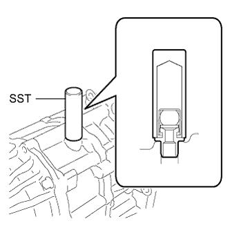
Using SST and a hammer, install the breather plug to the front transfer case.
- SST
- 09350-30020 ( 09350-07110 )
-
-
INSTALL TRANSFER DRAIN PLUG
-
Using a 10 mm hexagon socket wrench, install a new gasket and the drain plug to the rear transfer case.
- Torque:
- 49 N*m { 500 kgf*cm, 36 ft.*lbf }
-
-
INSTALL FILLER PLUG
-
Using a 10 mm hexagon socket wrench, install a new gasket and the filler plug to the rear transfer case.
- Torque:
- 49 N*m { 500 kgf*cm, 36 ft.*lbf }
-
-
INSTALL TRANSFER CASE PLUG
-
Using a 6 mm hexagon socket wrench, install 2 new O-rings and the 2 case plugs to the front transfer case.
- Torque:
- 19 N*m { 190 kgf*cm, 14 ft.*lbf }
-
-
INSTALL DYNAMIC DAMPER
-
Install the damper and 2 washers with the bolt to the rear transfer case.
- Torque:
- 30 N*m { 306 kgf*cm, 22 ft.*lbf }
-