TRANSFER ASSEMBLY REMOVAL

-
PRECAUTION
Note
After turning the power switch off, waiting time may be required before disconnecting the cable from the auxiliary battery terminal. Therefore, make sure to read the disconnecting the cable from the auxiliary battery terminal notice before proceeding with work Click here.
-
REMOVE FRONT WHEEL
-
REMOVE LUGGAGE COMPARTMENT MAT SUB-ASSEMBLY (w/ Spare Tire)

-
REMOVE DECK BOARD ASSEMBLY (w/o Spare Tire)

-
REMOVE DECK TRIM SIDE BOARD LH (w/o Spare Tire)
-

Detach the 2 clips and remove the deck trim side board LH.
-
-
REMOVE BATTERY SERVICE HOLE COVER LH
-

Text in Illustration *A for Standard *B for Ottoman *1 Fastening Tape Detach the clip, fastening tape and remove the battery service hole cover LH.
-
-
DISCONNECT CABLE FROM AUXILIARY BATTERY NEGATIVE TERMINAL
Note
When disconnecting the cable, some systems need to be initialized after the cable is reconnected Click here.
-
REMOVE SERVICE PLUG GRIP
-
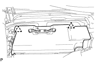
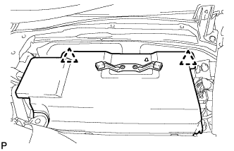
REMOVE V-BANK COVER SUB-ASSEMBLY
-

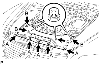
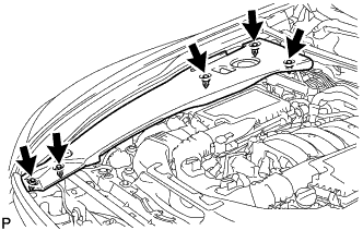
While using both hands, lift the rear side of the V-bank cover sub-assembly upwards to detach the 4 clips labeled B. Slide the V-bank cover sub-assembly towards the front of the vehicle to detach the 2 clips labeled A, and remove the V-bank cover sub-assembly.
Note
The V-bank cover sub-assembly may be damaged if its front and rear are lifted at the same time.
-
-
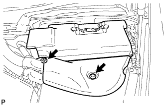
REMOVE AIR CLEANER INLET COVER SUB-ASSEMBLY
-
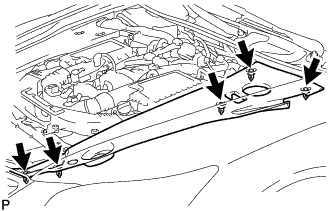
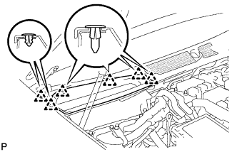
Remove the 5 clips labeled A.
-
Lift up the air cleaner inlet cover sub-assembly to detach the 4 clips labeled B, and remove the air cleaner inlet cover sub-assembly.
-
-
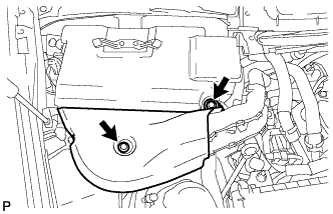
REMOVE NO. 1 AIR CLEANER INLET
-
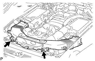
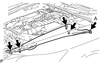
Remove the 2 bolts.
-
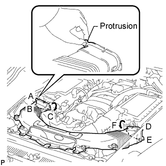
Hold the No. 1 air cleaner inlet by the protrusions labeled A and B, and detach the connections.
-
Rotate the No. 1 air cleaner inlet as shown in the illustration to detach the protrusion labeled C.
-
Hold the No. 1 air cleaner inlet by the protrusions labeled D and E, and detach the connections.
-
Rotate the No. 1 air cleaner inlet as shown in the illustration to detach the protrusion labeled F.
-
-
REMOVE ENGINE ROOM SIDE COVER RH
-
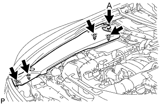
for LHD:
Remove the 5 clips and engine room side cover RH.
Note
Remove the clip labeled A by turning it to prevent the engine room side cover RH and bracket from being damaged.
Tech Tips
The clip labeled A cannot be removed from the engine room side cover RH.
-
for RHD:
Remove the 5 clips and engine room side cover RH.
-
-
REMOVE ENGINE ROOM SIDE COVER LH
-
for LHD:
Remove the 5 clips and engine room side cover LH.
-
for RHD:
Remove the 5 clips and engine room side cover LH.
Note
Remove the clip labeled A by turning it to prevent the engine room side cover LH and bracket from being damaged.
Tech Tips
The clip labeled A cannot be removed from the engine room side cover LH.
-
-
REMOVE COWL TOP VENTILATOR LOUVER RH (for LHD)
-
Remove the 6 clips and cowl top ventilator louver RH.
-
-
REMOVE COWL TOP VENTILATOR LOUVER LH (for RHD)
Tech Tips
Use the same procedures described for LHD vehicles.
-
REMOVE MOTOR CABLE COVER RH (for LHD)
-
Remove the 2 clips and motor cable cover RH.
-
-
REMOVE MOTOR CABLE COVER LH (for RHD)
-
Remove the 2 clips and motor cable cover LH.
-
-
REMOVE INVERTER COVER ASSEMBLY RH (for LHD)
-
Detach the 2 clips and remove the inverter cover assembly RH.
-
-
REMOVE INVERTER COVER ASSEMBLY LH (for RHD)
-
Detach the 2 clips and remove the inverter cover assembly LH.
-
-
REMOVE CONNECTOR COVER ASSEMBLY (for LHD)
CAUTION:
Wear insulating gloves.
-
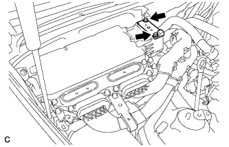
Using an insulated tool, remove the 2 bolts and connector cover assembly.
Note
-
Cover the hole where the cable was connected with tape or equivalent (non-residue type) to prevent entry of foreign matter.
-
Do not touch the high voltage connectors or terminals for 10 minutes after the service plug grip is removed.
-
-
-
CHECK TERMINAL VOLTAGE (for LHD)
CAUTION:
Wear insulating gloves.
-
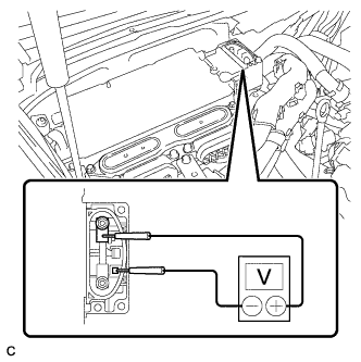
Using the voltmeter, measure the voltage between the terminals of the 2 phase connectors.
Standard voltage 0 V Tech Tips
Use measuring range of DC 750 V or more on the voltmeter.
-
-
INSTALL CONNECTOR COVER ASSEMBLY (for LHD)
CAUTION:
Wear insulating gloves.
-
Using an insulated tool, install the connector cover assembly with the 2 bolts.
- Torque:
- 8.0 N*m { 82 kgf*cm, 71 in.*lbf }
-
-
REMOVE CONNECTOR COVER ASSEMBLY (for RHD)
CAUTION:
Wear insulating gloves.
-
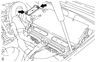
Using an insulated tool, remove the 2 bolts and connector cover assembly.
Note
-
Cover the hole where the cable was connected with tape or equivalent (non-residue type) to prevent entry of foreign matter.
-
Do not touch the high voltage connectors or terminals for 10 minutes after the service plug grip is removed.
-
-
-
CHECK TERMINAL VOLTAGE (for RHD)
CAUTION:
Wear insulating gloves.
-
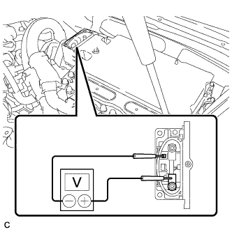
Using the voltmeter, measure the voltage between the terminals of the 2 phase connectors.
Standard voltage 0 V Tech Tips
Use measuring range of DC 750 V or more on the voltmeter.
-
-
INSTALL CONNECTOR COVER ASSEMBLY (for RHD)
CAUTION:
Wear insulating gloves.
-
Using an insulated tool, install the connector cover assembly with the 2 bolts.
- Torque:
- 8.0 N*m { 82 kgf*cm, 71 in.*lbf }
-
-
REMOVE FRONT CENTER FLOOR COVER (w/ Cover)
-
Remove the 3 screws, 2 bolts, clip and front center floor cover.
-
-
REMOVE NO. 2 ENGINE UNDER COVER
-
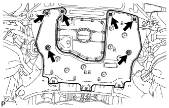
Remove the 4 screws, 2 clips and No. 2 engine under cover.
-
-
REMOVE FRONT WHEEL OPENING EXTENSION PAD RH
Tech Tips
Use the same procedure described for the LH side.
-
REMOVE FRONT WHEEL OPENING EXTENSION PAD LH
-
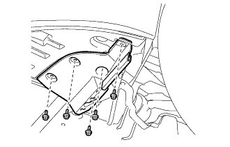
Remove the 5 screws and front wheel opening extension pad LH.
-
-
REMOVE NO. 1 ENGINE UNDER COVER
-
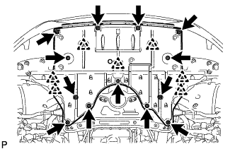
Remove the 13 screws, 7 clips and No. 1 engine under cover.
-
-
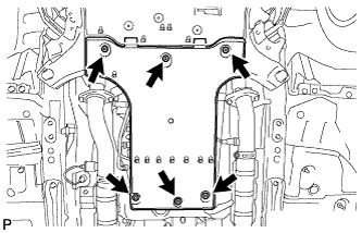
REMOVE FRONT LOWER SUSPENSION MEMBER PROTECTOR
-
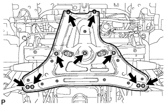
Remove the 9 bolts and front lower suspension member protector.
-
-
REMOVE FRONT EXHAUST PIPE ASSEMBLY
-
REMOVE PROPELLER SHAFT WITH CENTER BEARING ASSEMBLY
-
DISCONNECT FLOOR SHIFT GEAR SHIFTING ROD SUB-ASSEMBLY
-
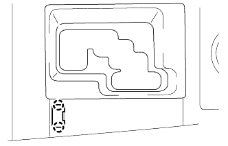
Using a small screwdriver, detach the 2 claws and remove the shift lock release button cover.
Tech Tips
Tape the screwdriver tip before use.
-
Depress the shift lock release button and move the shift lever to the N position.
-
Remove the nut and disconnect the floor shift gear shifting rod sub-assembly from the connecting rod swivel.
-
-
LOOSEN FRONT PROPELLER SHAFT ASSEMBLY
-
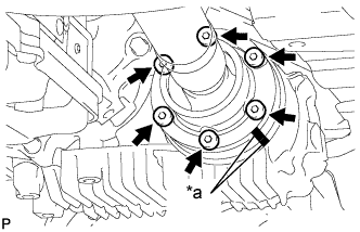
Text in Illustration *a Matchmark Put matchmarks on the transfer companion flange and front propeller shaft.
-
Using a 6 mm socket hexagon wrench, loosen the 6 bolts.
Note
Be careful not to damage the front propeller shaft.
-
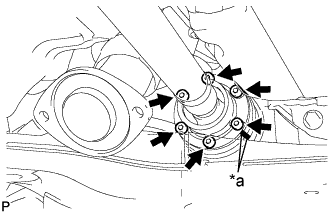
Text in Illustration *a Matchmark Put matchmarks on the front differential companion flange and front propeller shaft.
-
Using a 6 mm socket hexagon wrench, loosen the 6 bolts.
Note
Be careful not to damage the front propeller shaft.
-
-
DRAIN TRANSFER OIL
-
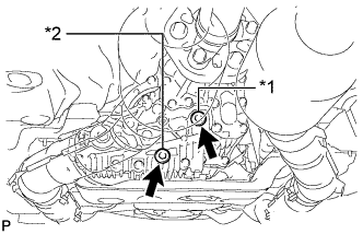
Text in Illustration *1 Filler plug *2 Drain plug Using a 10 mm hexagon wrench, remove the filler plug and gasket.
-
Using a 10 mm hexagon wrench, remove the drain plug and gasket, and drain the transfer oil.
-
-
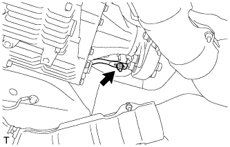
REMOVE TRANSFER ASSEMBLY
-
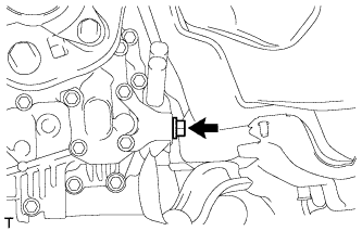
Remove the bolt and disconnect the ground cable.
-
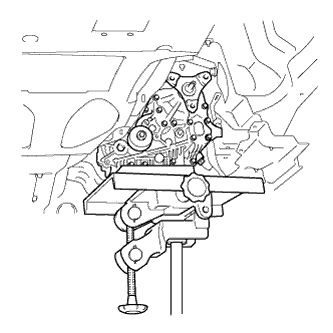
Using a jack and wooden blocks or equivalent, support the transfer.
Note
Do not set the wooden blocks or equivalent against the oil pan of the transmission.
-
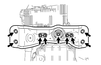
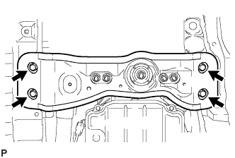
Remove the 4 bolts, 5 nuts, No. 3 rear engine mounting insulator and rear engine mounting member.
-
While supporting the front propeller shaft assembly by hand, remove the 12 bolts and 4 universal joint washers.
-
Remove the front propeller shaft assembly from each companion flange.
Note
Do not bend the front propeller shaft at an excessive angle.
-
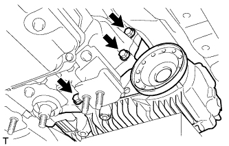
Remove the 3 bolts.
-
Install the rear engine mounting member and No. 3 rear engine mounting insulator with the 4 bolts and 5 nuts.
-
Set an engine lift and wooden blocks or equivalent against the rear engine mounting member and support the hybrid vehicle transmission.
Note
Do not set the wooden blocks or equivalent against the oil pan of the transmission.
-
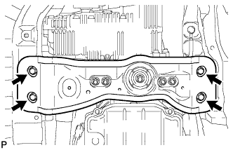
Remove the 4 bolts and disconnect the rear engine mounting member.
-
Slowly tilt the hybrid vehicle transmission away from the vehicle.
Note
Be careful of the exhaust manifold and wire harnesses when tilting the transmission.
-
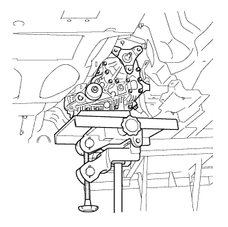
Make sure the wooden blocks or equivalent are set securely against the transfer with the jack.
-
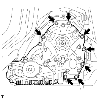
Remove the 8 bolts and transfer.
Note
-
Do not damage the oil seal.
-
Be careful not to drop the transfer assembly.
-
Be sure to perform this procedure with several people as the transfer assembly is very heavy.
-
-
Connect the rear engine mounting member with the 4 bolts.
-