DIFFERENTIAL CARRIER OIL SEAL REPLACEMENT

-
DRAIN REAR DIFFERENTIAL OIL
-
Stop the vehicle on a level place.
-
for Front Differential:
-
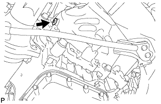
Using a 10 mm hexagon wrench, remove the filler plug and gasket.
-
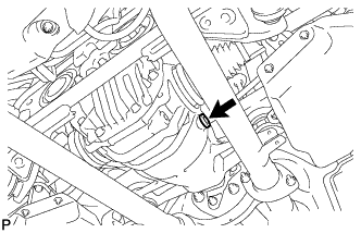
Using a 10 mm hexagon wrench, remove the drain plug and gasket, and drain the oil.
-
Using a 10 mm hexagon wrench, install a new gasket and the drain plug.
- Torque:
- 39 N*m { 398 kgf*cm, 29 ft.*lbf }
-
-
for Rear Differential:
-
Using a 10 mm hexagon wrench, remove the filler plug and gasket.
-
Using a 10 mm hexagon wrench, remove the drain plug and gasket, and drain the oil.
-
Using a 10 mm hexagon wrench, install a new gasket and the drain plug.
- Torque:
- 49 N*m { 500 kgf*cm, 37 ft.*lbf }
-
-
-
REMOVE DRIVE SHAFT ASSEMBLY
-
REMOVE REAR DIFFERENTIAL CARRIER ASSEMBLY
-
REMOVE REAR DIFFERENTIAL CARRIER COVER
-
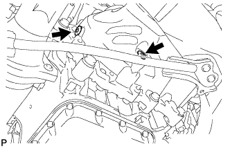
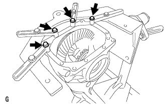
Remove the 8 bolts from the differential carrier cover.
-
Using a brass bar and hammer, remove the differential carrier cover from the differential carrier.
Note
-
Set the brass bar on the ribbed part of the differential carrier cover.
-
Do not damage the installation surface of the differential carrier.
-
-
-
FIX REAR DIFFERENTIAL CARRIER ASSEMBLY TO OVERHAUL STAND
-
Set the differential carrier to an overhaul stand as shown in the illustration.
Tech Tips
Install the differential carrier with the back surface of the ring gear facing the overhaul stand as shown in the illustration.
-
-
REMOVE REAR DIFFERENTIAL SIDE GEAR SHAFT OIL SEAL
-
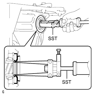
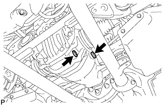
Using SST, remove the 2 oil seals.
- SST
- 09308-00010
-
-
REMOVE REAR DIFFERENTIAL SIDE GEAR SHAFT SHAFT SNAP RING
-
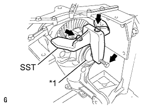
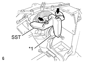
Text in Illustration *1 Disc Install the 2 bolts and SST to the differential carrier.
- SST
- 09571-50010
-
Tighten SST bolt until SST disc lightly touches the case bearing outer race.
-
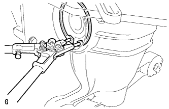
Install a dial indicator to the rear differential carrier.
-
Tighten SST bolt and alter the differential carrier's shape to create a 0.1 mm (0.00394 in.) clearance between the case bearing outer race and side gear shaft snap ring.
Note
Observe the dial indicator to ensure that the shape of the differential carrier does not change more than 0.2 mm (0.00787 in.).
Tech Tips
Approximately 0.1 mm (0.00394 in.) clearance between the case bearing outer race and the side gear shaft snap ring is sufficient for the washer to move slightly.
-
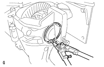
Using snap ring pliers, remove the side gear shaft snap ring on the ring gear tooth side.
Tech Tips
-
For reassembly purposes, measure the thickness of the differential side gear shaft snap ring, and record the result.
-
Place distinguishing marks on the left and right side differential side gear shaft snap rings to distinguish them (back surface side, tooth side). Then store them separately.
-
-
Remove the dial indicator from the differential carrier.
-
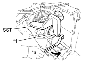
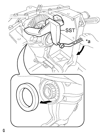
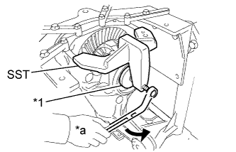
Text in Illustration *1 Disc *a Turn Loosen SST bolt until SST disc separates from the tooth side of the differential case bearing outer race.
Tech Tips
Do not remove SST.
-
-
REMOVE REAR DIFFERENTIAL SIDE GEAR SHAFT SHAFT SNAP RING
-
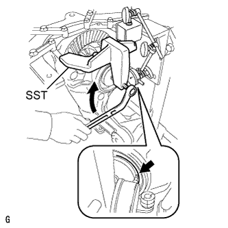
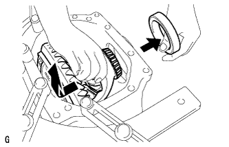
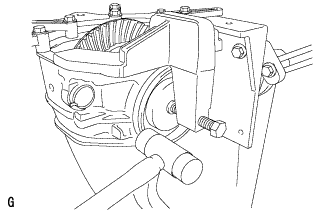
Using SST and a hammer, create a clearance between the case bearing outer race on the back surface of the ring gear and side gear shaft snap ring.
- SST
- 09608-32010
- 09950-70010 ( 09951-07200 )
Tech Tips
The clearance is not visible, but tapping SST with a hammer 3 or 4 times should be enough.
-
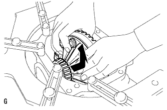
Using snap ring pliers, remove the side gear shaft snap ring on the back surface of the ring gear.
Tech Tips
-
For reassembly purposes, measure the thickness of the differential side gear shaft snap ring, and record the result.
-
Place distinguishing marks on the left and right side differential side gear shaft snap rings to distinguish them (back surface side, tooth side). Then store them separately.
-
-
-
REMOVE REAR DIFFERENTIAL CASE BEARING OUTER RACE
-
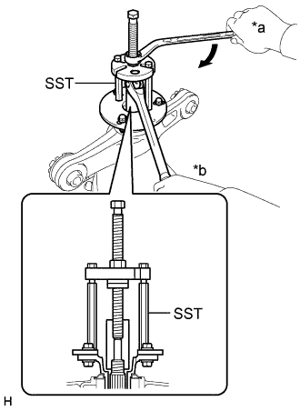
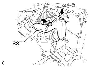
Text in Illustration *a Turn Tighten SST bolt and push out the case bearing outer race on the ring gear back surface side.
- SST
- 09571-50010
Note
Do not drop the case bearing outer race.
Tech Tips
-
For reassembly purposes, mark the installation positions of the differential case bearing outer race and differential side gear shaft snap ring.
-
Place distinguishing marks on the left and right side differential case bearing outer races to distinguish them (back surface side, tooth side). Then store them separately.
-

Text in Illustration *1 Disc Remove the 2 bolts and SST from the differential carrier.
-
-
REMOVE REAR DIFFERENTIAL CASE BEARING OUTER RACE
-
Raise the ring gear of the differential case slightly and remove the ring gear tooth side case bearing outer race.
Note
Do not drop the case bearing outer race.
Tech Tips
-
For reassembly purposes, mark the installation positions of the differential case bearing outer race and differential side gear shaft snap ring.
-
Place distinguishing marks on the left and right side differential case bearing outer races to distinguish them (back surface side, tooth side). Then store them separately.
-
-
-
REMOVE REAR DIFFERENTIAL CASE SUB-ASSEMBLY
-
Remove the rear differential case from the differential carrier as shown in the illustration.
Note
Do not damage the case bearing and ring gear.
-
-
REMOVE REAR DRIVE PINION NUT
-
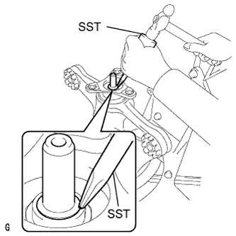
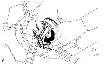
Using SST and a hammer, unstake the staked part of the drive pinion nut.
- SST
- 09930-00010
Note
-
Do not grind the tip of SST with a grinder, etc.
-
Completely unstake the drive pinion nut to prevent damaging the threads of the drive pinion.
-
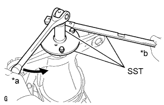
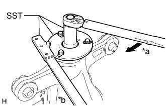
Text in Illustration *a Turn *b Hold Using SST, fix the companion flange in place.
- SST
- 09330-00021
- 09950-30012 ( 09955-03040 )
-
While supporting the overhaul attachment, using SST, remove the rear drive pinion nut.
- SST
- 09229-55010
-
-
REMOVE REAR DRIVE PINION COMPANION FLANGE REAR SUB-ASSEMBLY
-
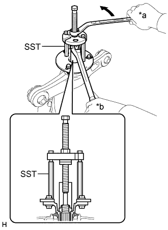
Text in Illustration *a Turn *b Hold Using SST, remove the companion flange from the differential carrier.
- SST
- 09950-30012 ( 09951-03010, 09953-03010, 09954-03010, 09955-03040, 09956-03060 )
Tech Tips
Before using SST center bolt, apply hypoid gear oil to its threads and tip.
-
-
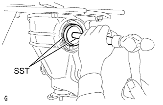
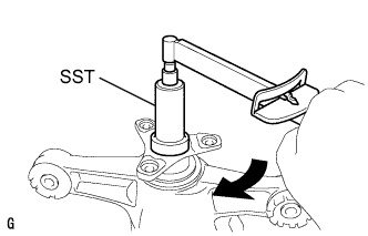
REMOVE REAR DIFFERENTIAL CARRIER OIL SEAL
-
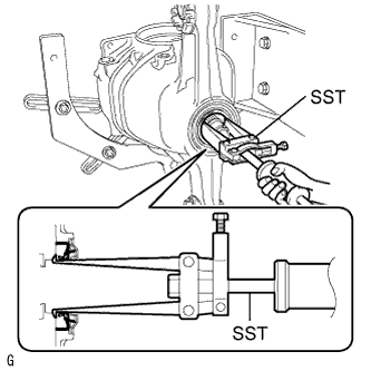
Using SST, remove the oil seal from the differential carrier.
- SST
- 09308-00010
-
-
REMOVE REAR DIFFERENTIAL DRIVE PINION OIL SLINGER
-
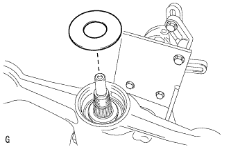
Using a magnet hand, remove the oil slinger from the differential carrier.
-
-
REMOVE DIFFERENTIAL DRIVE PINION WITH BEARING INNER RACE
-
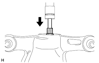
Using a press, press out the drive pinion from the differential carrier.
Note
Do not drop the drive pinion.
-
-
REPLACE REAR DIFFERENTIAL DRIVE PINION BEARING SPACER
-
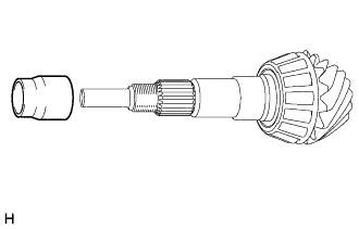
Replace the drive pinion bearing spacer with a new one and install it to the drive pinion.
Tech Tips
The bearing spacer can be installed facing either direction.
-
-
INSTALL DIFFERENTIAL DRIVE PINION WITH BEARING INNER RACE
-
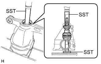
Using SST and a press, press in the differential drive pinion to the differential carrier.
- SST
- 09316-60011 ( 09316-00011, 09316-00041 )
- 09608-04031
-
-
INSTALL REAR DIFFERENTIAL DRIVE PINION OIL SLINGER
-
Install the differential drive pinion oil slinger to the differential drive pinion.
-
-
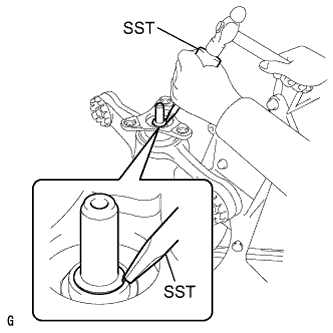
INSTALL REAR DIFFERENTIAL CARRIER OIL SEAL
-
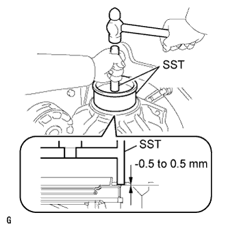
Using SST and a hammer, tap in a new oil seal.
- SST
- 09316-60011 ( 09316-00011 )
- 09710-04101
Note
-
Tap the oil seal uniformly so that the oil seal is straight.
-
Do not excessively tap the oil seal.
-
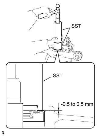
Using a vernier caliper, measure the depth of the oil seal.
Standard depth -0.5 to 0.5 mm (-0.0197 to 0.0197 in.) Note
-
Measure at 3 or more areas around the circumference of the oil seal.
-
Make sure difference between the maximum and minimum measured values is less than 0.65 mm (0.0256 in.), as a greater difference may lead to oil leaks.
-
-
-
INSTALL REAR DRIVE PINION COMPANION FLANGE REAR SUB-ASSEMBLY
-
Text in Illustration *a Turn *b Hold Using SST, install the companion flange to the differential carrier.
- SST
- 09950-30012 ( 09951-03010, 09953-03010, 09954-03010, 09955-03040, 09956-03060 )
Note
Perform this procedure after aligning the companion flange with the spline of the drive pinion.
Tech Tips
Before using SST center bolt, apply hypoid gear oil to its threads and tip.
-
Coat the threads of a new drive pinion nut with hypoid gear oil LSD.
-
Text in Illustration *a Turn *b Hold Use SST to hold the companion flange.
- SST
- 09950-30012 ( 09955-03040 )
-
Using SST and a torque wrench, tighten the drive pinion nut while checking the starting torque of the drive pinion.
- SST
- 09229-55010
- 09330-00021
Maximum torque 490 N*m (5000 kgf*cm, 361 ft.*lbf) or less Note
-
Do not overtighten the nut, as the threads will become damaged.
-
Perform the tightening while supporting the overhaul attachment.
Tech Tips
-
Tighten the nut with a force of 100 N*m (1020 kgf*cm, 74 ft.*lbf) and keep tightening while checking the starting torque of the drive pinion.
-
Apply hypoid gear oil LSD to the threads of the nut and drive pinion.
-
-
INSTALL REAR DIFFERENTIAL CASE SUB-ASSEMBLY
-
Insert the differential case from the ring gear tooth side.
Note
Do not damage the case bearing inner race and ring gear.
-
-
INSTALL REAR DIFFERENTIAL CASE BEARING OUTER RACE
-
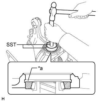
Text in Illustration *a Groove Using SST and a hammer, tap in the ring gear tooth side case bearing outer race.
- SST
- 09608-32010
- 09950-70010 ( 09951-07200 )
Tech Tips
Tap in the case bearing outer race until half of the side gear shaft snap ring groove of the differential carrier can be seen.
-
Text in Illustration *1 Disc Install SST to the differential carrier with the 2 bolts.
- SST
- 09571-50010
-
Tighten SST bolt until SST disc lightly touches the case bearing outer race.
-
Using SST and a hammer, tap in the ring gear back surface side case bearing outer race.
- SST
- 09608-32010
- 09950-70010 ( 09951-07200 )
Tech Tips
Tap in the case bearing outer race until it touches the case bearing inner race roller bearing.
-
-
INSTALL REAR DIFFERENTIAL SIDE GEAR SHAFT SHAFT SNAP RING
-
Using snap ring pliers, install the side gear shaft snap ring in the differential carrier on the ring gear back surface side.
Note
Check that the differential side gear shaft snap ring is securely fitted into the groove.
Tech Tips
Use the side gear shaft snap ring that was used during the tooth contact adjustment.
-
Install a dial indicator on the differential carrier.
-
Tighten SST bolt, and push in the differential case.
Tech Tips
-
Try to set the dial indicator as close as possible to the differential carrier cover side (upper side in illustration) of the differential case bearing outer race.
-
Approximate 0.1 mm (0.00394 in.) clearance between the differential case bearing outer race and the differential side gear shaft snap ring only needs to be enough so that the differential side gear shaft snap ring can move slightly.
Note
Observe the dial indicator to ensure that the shape of the differential carrier does not change more than 0.2 mm (0.00787 in.).
-
-
Remove the dial indicator and using snap ring pliers, install the side gear shaft snap ring on the ring gear tooth side.
Tech Tips
Use the side gear shaft snap ring that was used during the tooth contact adjustment.
-
Text in Illustration *1 Disc *a Turn Loosen SST bolt until SST disc separates from the tooth side of the differential case bearing outer race.
-
Tap the differential carrier on the ring gear tooth side using a plastic-faced hammer to stabilize the case bearing.
-
Remove the 2 bolts and SST from the differential carrier.
-
-
ADJUST DRIVE PINION PRELOAD
-
Using SST and a torque wrench, measure the preload.
- SST
- 09229-55010
Standard total preload (at starting) 1.25 to 1.65 N*m (13 to 16 kgf*cm, 11 to 14 in.*lbf) Tech Tips
-
For a more accurate measurement, rotate the flange forward and backward several times before the measurement.
-
Check the starting torque of the drive pinion for use with the total preload inspection.
Note
-
The bearing spacer is made of plastic and changes shape when used. If the starting torque of the drive pinion is exceeded by mistake, make sure to replace the bearing spacer with a new one.
-
If the starting torque of the drive pinion is exceeded, replace the bearing spacer.
-
If the starting torque of the drive pinion is insufficient, tighten the drive pinion nut 5 to 10° at a time.
Maximum torque 490 N*m (5000 kgf*cm, 361 ft.*lbf) or less Repeat the adjustment as necessary until the starting torque matches the specified torque.
-
If the tightening torque of the pinion nut exceeds the specified torque but the drive pinion starting torque is still insufficient, loosen the pinion nut. Then check if the pinion nut and drive pinion threads are damaged.
-
If there are no problems, replace the bearing spacer, apply hypoid gear oil LSD to its threads and repeat the procedure above.
-
-
INSPECT TOTAL PRELOAD
-
Using SST and a torque wrench, measure the preload with the teeth of the drive pinion and ring gear in contact.
- SST
- 09229-55010
Standard total preload New bearing 1.87 to 3.39 N*m (19 to 34 kgf*cm, 17 to 30 in.*lbf) Reused bearing 1.71 to 2.87 N*m (18 to 29 kgf*cm, 16 to 25 in.*lbf)
-
-
STAKE REAR DRIVE PINION NUT
-
Using a SST and a hammer, stake the drive pinion nut.
- SST
- 09930-00010
-
-
INSTALL REAR DIFFERENTIAL SIDE GEAR SHAFT OIL SEAL
-
Using SST and a hammer, install 2 new oil seals.
- SST
- 09223-15030
- 09950-70010 ( 09951-07150 )
Standard depth -0.5 to 0.5 mm (-0.0197 to 0.0196 in.) Note
-
Tap the oil seal uniformly so that the oil seal is straight.
-
After the installation, check that the oil seal has been tapped securely onto the differential.
-
-
REMOVE REAR DIFFERENTIAL CARRIER ASSEMBLY FROM OVERHAUL STAND
-
Remove the differential carrier from the overhaul stand.
-
-
INSTALL REAR DIFFERENTIAL CARRIER COVER
-
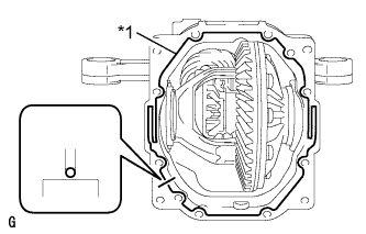
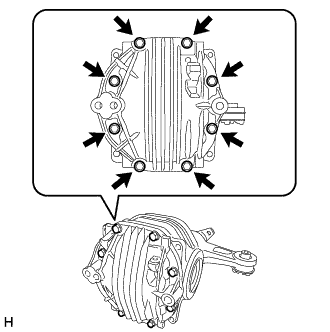
Text in Illustration *1 Seal Packing Apply seal packing to the differential carrier as shown in the illustration.
Seal packing Toyota Genuine Seal Packing 1281, Three bond 1281 or equivalent Note
-
Apply the seal packing in a continuous line, approximately 2 to 3 mm (0.0787 to 0.118 in.) in diameter.
-
Overlap the seal packing at least 10 mm (0.394 in.) at the beginning and the end of application.
-
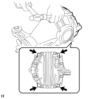
Install the differential carrier cover within 3 minutes of application.
-
-
Install the differential carrier cover with the 8 bolts.
- Torque:
- 47 N*m { 479 kgf*cm, 35 ft.*lbf }
Note
Do not fill the oil or drive immediately after installing the differential carrier cover. Leave the vehicle for at least 1 hour. Also, avoid sudden acceleration and deceleration for at least 12 hours after application.
-
-
CLEAN REAR DIFFERENTIAL CARRIER ASSEMBLY
-
INSTALL DRIVE SHAFT ASSEMBLY
-
ADD REAR DIFFERENTIAL OIL
-
for Front Differential:
-
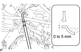
Add differential oil so that the oil level is between 0 to 5 mm (0 to 0.197 in.) from the bottom lip of the differential filler plug hole.
Note
-
Too much or too little oil will lead to differential problems.
-
After changing the oil, drive the vehicle and then check the oil level again.
Oil type Toyota Genuine Differential Gear Oil LT 75W-85 GL-5 or equivalent. Capacity 0.7 to 0.8 liters (0.74 to 0.84 US qts., 0.62 to 0.70 Imp. qts.) -
-
Using a 10 mm hexagon wrench, install a new gasket and the filler plug.
- Torque:
- 39 N*m { 398 kgf*cm, 29 ft.*lbf }
-
-
for Rear Differential:
-
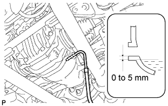
Add differential oil so that the oil level is between 0 to 5 mm (0 to 0.196 in.) from the bottom lip of the differential filler plug hole.
Note
-
Too much or too little oil will lead to differential problems.
-
After changing the oil, drive the vehicle and then check the oil level again.
Oil type Toyota Genuine Differential Gear Oil LX 75W-85 GL-5 or equivalent Capacity 1.3 to 1.4 liters (1.38 to 1.47 US qts., 1.15 to 1.23 Imp. qts.) -
-
Using a 10 mm hexagon wrench, install a new gasket and the filler plug.
- Torque:
- 49 N*m { 500 kgf*cm, 36 ft.*lbf }
-
-