SHIFT LEVER INSTALLATION

-
INSTALL TRANSMISSION FLOOR SHIFT ASSEMBLY
-
Install the transmission floor shift assembly with the 4 bolts.
- Torque:
- 8.3 N*m { 85 kgf*cm, 74 in.*lbf }
-
for LHD:
Connect the 2 connectors and 7 wire harness clamps to the transmission floor shift assembly.
-
for RHD:
Connect the 3 connectors and 6 wire harness clamps to the transmission floor shift assembly.
-
-
INSTALL NO. 1 CONSOLE BOX DUCT
-
Install the No. 1 console box duct with the 2 clips.
-
Connect the 2 wire harness clamps to the No. 1 console box duct.
-
-
INSTALL CONSOLE BOX ASSEMBLY
for 5-passenger with Ottoman: Click here.
w/o Rear Entertainment System: Click here.
w/ DVD player: Click here
-
CONNECT FLOOR SHIFT GEAR SHIFTING ROD SUB-ASSEMBLY
-
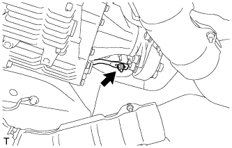
Temporarily connect the shifting rod to the connecting rod swivel with the nut.
Tech Tips
The nut will be tightened to a specified torque during the shift lever position adjustment procedure.
-
Attach the 2 claws to install the shift lock release button cover.
-
-
CONNECT CABLE TO AUXILIARY BATTERY NEGATIVE TERMINAL
Note
When disconnecting the cable, some systems need to be initialized after the cable is reconnected Click here.
-
ADJUST SHIFT LEVER POSITION
-
Remove the nut, and disconnect the floor shift gear shifting rod sub-assembly.
-

Turn the control shaft lever counterclockwise until it stops. Next, turn the control shaft lever clockwise 2 notches to set it to the N position.
-
Move the shift lever to the N position and tighten the nut while lightly pushing the shift lever toward the R position.
- Torque:
- 13 N*m { 130 kgf*cm, 9 ft.*lbf }
Note
Do not push the shift lever too hard.
-
Check that the shift lever moves smoothly and the shift lever and gear operate correctly.
-
-
INSPECT SHIFT LEVER OPERATION
-
When moving the shift lever from the P position to the R position with the power switch on (IG) and the brake pedal depressed, make sure that it moves smoothly and correctly into position.
-
Turn the power switch on (READY) and make sure that the vehicle moves forward when the shift lever is moved from the N position to the D position and moves rearward when the shift lever is moved to the R position. If the operation cannot be performed as specified, inspect the shift lever position sensor and check the shift lever assembly installation condition.
-
-
INSTALL BATTERY SERVICE HOLE COVER LH
-

Text in Illustration *A for Standard *B for Ottoman Attach the battery service hole cover LH with the clip and fastening tape.
-
-
INSTALL DECK TRIM SIDE BOARD LH (w/o Spare Tire)
-

Attach the 2 clips to install the deck trim side board LH.
-
-
INSTALL DECK BOARD ASSEMBLY (w/o Spare Tire)

-
INSTALL LUGGAGE COMPARTMENT MAT SUB-ASSEMBLY (w/ Spare Tire)
