HYBRID VEHICLE TRANSMISSION INSTALLATION

-
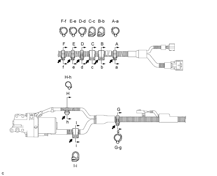
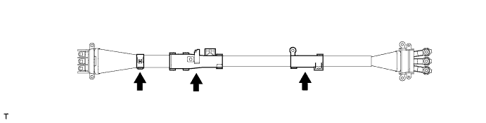
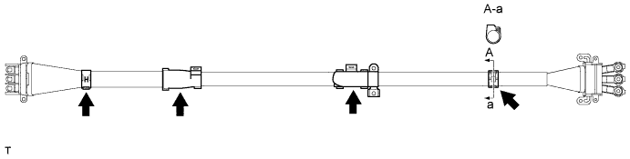
INSTALL WIRE HARNESS CLAMP
-
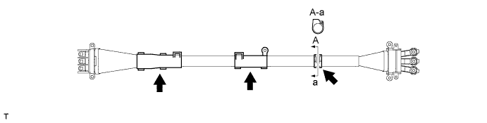
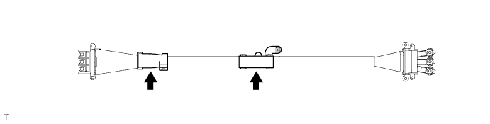
Align the matchmarks and install 9 new clamps to the wire.
-
-
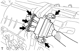
INSTALL HYBRID VEHICLE TRANSMISSION ASSEMBLY
-
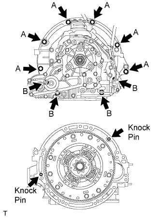
Make sure that the knock pins are installed on the engine.
-
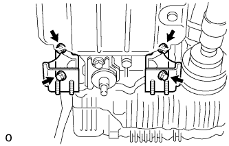
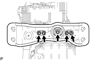
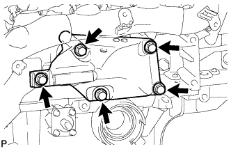
While keeping the engine and the hybrid vehicle transmission assembly horizontal, align the knock pins and the knock pin holes, and then tighten the 10 bolts shown in the illustration.
- Torque:
- for Bolt A
- 71 N*m { 724 kgf*cm, 52 ft.*lbf }
- for Bolt B
- 37 N*m { 377 kgf*cm, 27 ft.*lbf }
Note
-
Do not forcibly pry out the hybrid vehicle transmission assembly.
-
Do not apply grease either to the splines or to the input shaft.
Bolt Diameter Bolt length A 12 mm (0.47 in.) 50 mm (1.97 in.) B 10 mm (0.39 in.) 43 mm (1.69 in.)
-
-
INSTALL STARTER HOLE INSULATOR
-
Install the starter hole insulator with the 2 bolts.
- Torque:
- 58 N*m { 591 kgf*cm, 43 ft.*lbf }
Diameter Bolt length 10 mm (0.39 in.) 65 mm (2.56 in.)
-
-
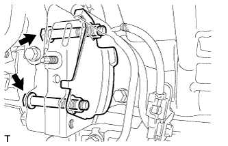
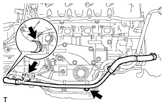
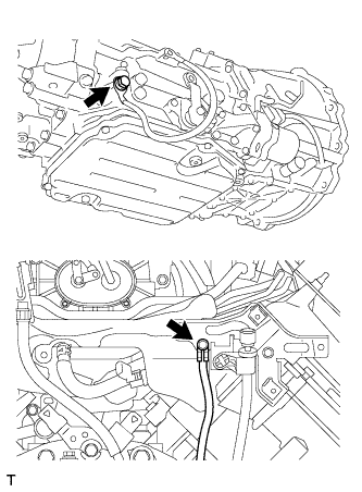
INSTALL TRANSMISSION BREATHER HOSE SUB-ASSEMBLY
-
Install the breather hose.
-
Install the transmission breather hose with the 2 bolts.
- Torque:
- 7.0 N*m { 71 kgf*cm, 62 in.*lbf }
-
Connect the clamp and clip.
-
-
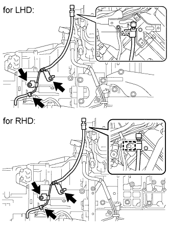
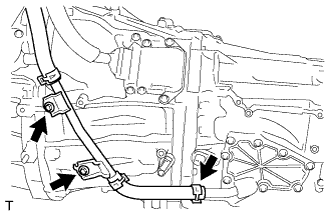
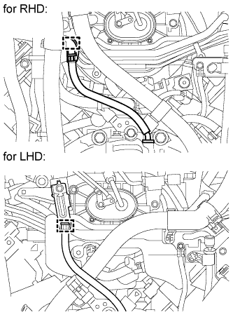
INSTALL NO. 1 HV WATER PUMP OUTLET PIPE (for LHD)
-
Install the No. 1 hv water pump outlet pipe with the 2 bolts.
- Torque:
- 22 N*m { 224 kgf*cm, 16 ft.*lbf }
-
Secure the hose with the clip.
-
-
INSTALL NO. 2 MOTOR COOLING PIPE (for RHD)
-
Install the No. 2 motor cooling pipe with the 2 bolts.
- Torque:
- 22 N*m { 224 kgf*cm, 16 ft.*lbf }
-
Secure the hose with the clip.
-
-
INSTALL NO. 1 MOTOR COOLING PIPE (for LHD)
-
Install the No. 1 motor cooling pipe with the 2 bolts.
- Torque:
- 22 N*m { 224 kgf*cm, 16 ft.*lbf }
-
Secure the hose with the clip.
Note
Do not install the clip close to the outlet port of the union pipe.
-
-
INSTALL NO. 1 INVERTER COOLING PIPE (for RHD)
-
Install the No. 1 inverter cooling pipe with the 2 bolts.
- Torque:
- 22 N*m { 224 kgf*cm, 16 ft.*lbf }
-
Secure the hose with the clip.
Note
Do not install the clip close to the outlet port of the union pipe.
-
-
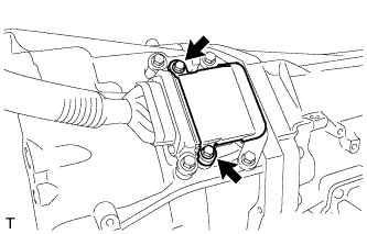
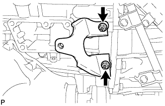
INSTALL REAR NO. 2 ENGINE MOUNTING INSULATOR
-
Install the mounting insulator with the 2 bolts.
- Torque:
- 30 N*m { 306 kgf*cm, 22 ft.*lbf }
-
-
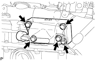
INSTALL REAR NO. 1 ENGINE MOUNTING INSULATOR
-
Install the 2 mounting insulators with the 4 bolts.
- Torque:
- 30 N*m { 306 kgf*cm, 22 ft.*lbf }
-
-
INSTALL REAR ENGINE MOUNTING MEMBER
-
Install the mounting member and No. 3 mounting insulator with the 5 nuts.
- Torque:
- 38 N*m { 387 kgf*cm, 28 ft.*lbf }
-
-
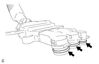
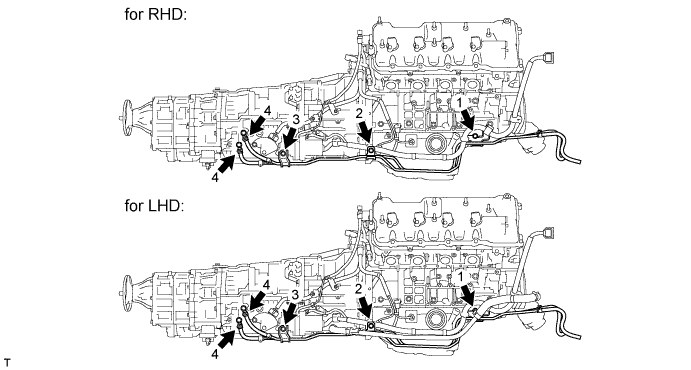
INSTALL GENERATOR CABLE PROTECTOR
-
for LHD:
-
Align the matchmarks and install the 3 generator cable protectors to the generator cable.
Note
Install the protectors to the positions indicated by the matchmarks that placed before removing the protectors.
-
-
for RHD:
-
Align the matchmarks and install the 2 generator cable protectors to the generator cable.
Note
Install the protectors to the positions indicated by the matchmarks that placed before removing the protectors.
-
-
-
INSTALL MOTOR CABLE PROTECTOR
-
for LHD:
-
Align the matchmarks and install the 3 motor cable protectors to the motor cable.
Note
Install the protectors to the positions indicated by the matchmarks that placed before removing the protectors.
-
-
for RHD:
-
Align the matchmarks and install the 4 motor cable protectors to the motor cable.
Note
Install the protectors to the positions indicated by the matchmarks that placed before removing the protectors.
-
-
-
INSTALL MOTOR CABLE
Note
When installing the motor cable, minimize bending of the cable end on the transmission side.
-
Install the 3 O-rings to the terminal cables.
Note
-
Make sure that the O-rings are not damaged.
-
Do not allow the O-rings to rest out of the grooves.
-
Do not allow any ATF to adhere to the O-rings.
-
Make sure that the O-rings are not twisted.
-
-
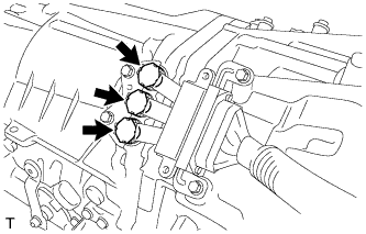
Using a 5 mm hexagon wrench, tighten the 3 bolts.
- Torque:
- 8.0 N*m { 82 kgf*cm, 71 in.*lbf }
Note
-
When installing the motor cable, align the projections on the cable with the terminal grooves.
-
Do not apply force to the cable when installing it.
-
Do not allow the cable to twist when installing it.
-
When installing the motor cable, minimize bending of the cable end on the transmission side.
-
Protect the terminal cables and the installation components from water or foreign objects.
-
Make sure that the O-rings do not get pinched between the parts.
-
Make sure that the tightening torque is between 6.4 and 9.6 N*m (65 and 98 kgf*cm, 57 and 85 in.*lbf).
Tech Tips
To avoid putting too much pressure on the motor cable and bending its end, hold the end of the motor cable in one hand and use the other hand to line the motor cable up and install it against the side of the engine.
-
Install the 2 bolts.
- Torque:
- 8.0 N*m { 82 kgf*cm, 71 in.*lbf }
Note
Make sure that the tightening torque is between 6.4 and 9.6 N*m (65 and 98 kgf*cm, 57 and 85 in.*lbf).
-
Install 3 new terminal caps to the hybrid vehicle transmission assembly.
Note
-
Make sure that the O-rings are not damaged.
-
Do not allow any ATF to adhere to the O-rings.
-
Make sure that the O-rings are not twisted.
-
Make sure that the O-rings do not get pinched between the parts.
-
After installing the terminal caps, make sure that the locks are securely engaged.
-
-
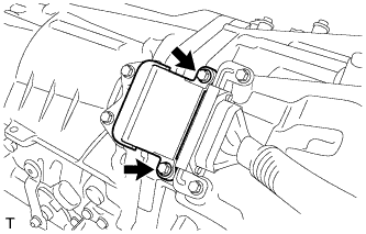
Install the connector cover with the 2 bolts.
- Torque:
- 8.0 N*m { 82 kgf*cm, 71 in.*lbf }
Note
Make sure that the tightening torque is between 6.4 and 9.6 N*m (65 and 98 kgf*cm, 57 and 85 in.*lbf).
-
-
INSTALL GENERATOR CABLE
Note
When installing the generator cable, minimize bending of the cable end on the transmission side.
-
Install the 3 O-rings to the terminal cables.
Note
-
Make sure that the O-rings are not damaged.
-
Do not allow the O-rings to rest out of the grooves.
-
Do not allow any ATF to adhere to the O-rings.
-
Make sure that the O-rings are not twisted.
-
-
Using a 5 mm hexagon wrench, tighten the 3 bolts.
- Torque:
- 8.0 N*m { 82 kgf*cm, 71 in.*lbf }
Note
-
When installing the generator cable, align the projections on the cable with the terminal grooves.
-
Do not apply force to the cable when installing it.
-
Do not allow the cable to twist when installing it.
-
Protect the terminal cables and the installation components from water or foreign objects.
-
Make sure that the O-rings do not get pinched between the parts.
-
Make sure that the tightening torque is between 6.4 and 9.6 N*m (65 and 98 kgf*cm, 57 and 85 in.*lbf).
Tech Tips
To avoid putting too much pressure on the generator cable and bending its end, hold the end of the generator cable in one hand and use the other hand to line the generator cable up and install it against the side of the engine.
-
Install the 2 bolts.
- Torque:
- 8.0 N*m { 82 kgf*cm, 71 in.*lbf }
Note
Make sure that the tightening torque is between 6.4 and 9.6 N*m (65 and 98 kgf*cm, 57 and 85 in.*lbf).
-
Install 3 new terminal caps to the hybrid vehicle transmission assembly.
Note
-
Make sure that the O-rings are not damaged.
-
Do not allow any ATF to adhere to the O-rings.
-
Make sure that the O-rings are not twisted.
-
Make sure that the O-rings do not get pinched between the parts.
-
After installing the terminal caps, make sure that the locks are securely engaged.
-
-
Install the connector cover with the 2 bolts.
- Torque:
- 8.0 N*m { 82 kgf*cm, 71 in.*lbf }
Note
Make sure that the tightening torque is between 6.4 and 9.6 N*m (65 and 98 kgf*cm, 57 and 85 in.*lbf).
-
-
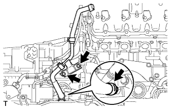
INSTALL OIL COOLER TUBE
-
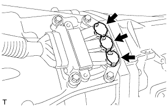
Install the oil cooler tube with the 2 clips and the 3 bolts in the order shown in the illustration.
- Torque:
- 12 N*m { 122 kgf*cm, 9 ft.*lbf }
-
-
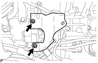
INSTALL TRANSMISSION MOTOR CABLE CLAMP BRACKET
-
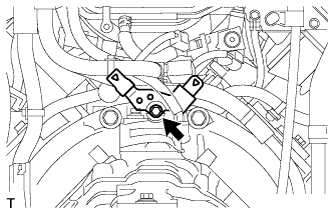
Install the transmission motor cable clamp bracket with the bolt.
- Torque:
- 8.0 N*m { 82 kgf*cm, 71 in.*lbf }
-
-
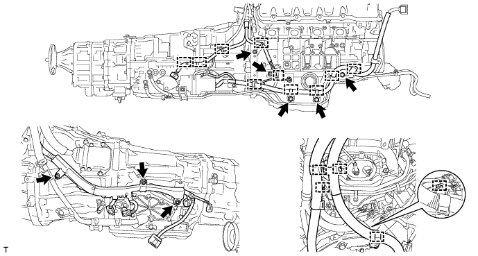
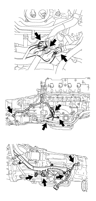
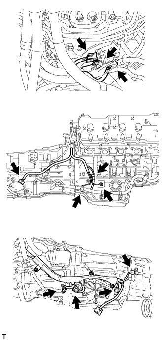
CONNECT WIRE HARNESS
Note
When installing the motor cable and generator cable, minimize bending of the cable end on the transmission side.
-
for LHD:
-
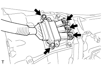
Install the wire harness with the 6 bolts.
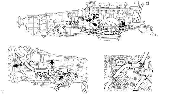
- Torque:
- 10 N*m { 102 kgf*cm, 9 ft.*lbf }
-
Connect the 15 clamps.
-
Install the 2 ground cables with the 2 bolts.
- Torque:
- 10 N*m { 102 kgf*cm, 9 ft.*lbf }
-
-
for RHD:
-
Install the wire harness with the 8 bolts.
- Torque:
- 10 N*m { 102 kgf*cm, 9 ft.*lbf }
-
Connect the 15 clamps.
-
Install the 2 ground cables with the 2 bolts.
- Torque:
- 10 N*m { 102 kgf*cm, 9 ft.*lbf }
-
-
-
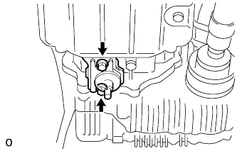
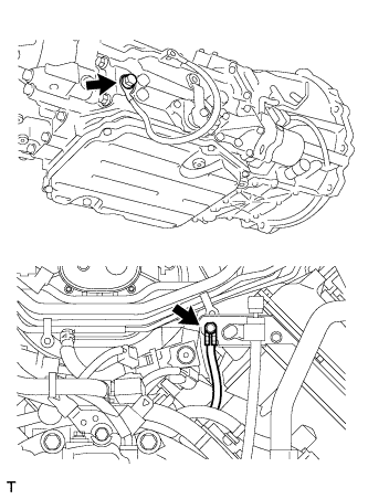
INSTALL TRANSMISSION BREATHER HOSE SUB-ASSEMBLY
-
Install a new O-ring.
-
Coat the O-ring with ATF.
-
Install the transmission breather hose sub-assembly.
-
Connect the clamp.
-
-
CONNECT CONNECTOR
-
for LHD:
-
Connect the 11 wire harness connectors.
-
-
for RHD:
-
Connect the 11 wire harness connectors.
-
-
-
INSTALL NO. 3 COVER SUB-ASSEMBLY
-
Install the No. 3 cover sub-assembly with the 2 clips.
-
-
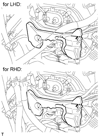
INSTALL INVERTER MOTOR CABLE CLAMP BRACKET
-
for LHD:
-
Install the 2 inverter motor cable clamp brackets to the motor cable.
-
Connect the generator cable to the motor cable.
-
-
for RHD:
-
Install the 2 inverter motor cable clamp brackets to the motor cable.
-
-
-
INSTALL FRONT PROPELLER SHAFT ASSEMBLY
-
Using a 6 mm socket hexagon wrench, tighten the front propeller shaft with the 6 bolts.
- Torque:
- 25 N*m { 255 kgf*cm, 18 ft.*lbf }
Note
Be careful not to damage the front propeller shaft.
-
Using a 6 mm socket hexagon wrench, tighten the front propeller shaft with the 6 bolts.
- Torque:
- 25 N*m { 255 kgf*cm, 18 ft.*lbf }
Note
Be careful not to damage the front propeller shaft.
-
-
INSTALL FRONT NO. 2 ENGINE MOUNTING BRACKET LH
-
Temporarily install the front No. 2 engine mounting bracket LH with the 2 nuts.
-
Temporarily install the front No. 1 engine mounting bracket LH with the 5 bolts.
-
Tighten the 2 nuts.
- Torque:
- 21 N*m { 214 kgf*cm, 15 ft.*lbf }
-
Remove the 5 bolts and front No. 1 engine mounting bracket LH.
-
-
INSTALL FRONT NO. 2 ENGINE MOUNTING BRACKET RH
-
Temporarily install the front No. 2 engine mounting bracket RH with the 2 nuts.
-
Temporarily install the front No. 1 engine mounting bracket RH with the 5 bolts.
-
Tighten the 2 nuts.
- Torque:
- 21 N*m { 214 kgf*cm, 15 ft.*lbf }
-
Remove the 5 bolts and front No. 1 engine mounting bracket RH.
-
-
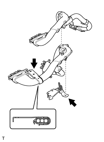
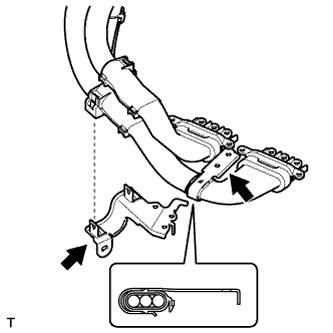
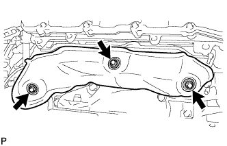
INSTALL EXHAUST MANIFOLD SUB-ASSEMBLY LH
-
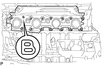
Place a new gasket on the cylinder head with the "B" mark facing the manifold side.
Note
Be careful of the installation direction.
-
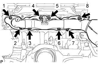
Temporarily install the exhaust manifold, and then uniformly tighten 8 new nuts in several steps, in the sequence shown in the illustration.
- Torque:
- 21 N*m { 214 kgf*cm, 15 ft.*lbf }
-
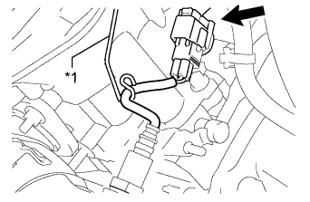
Text in Illustration *1 Bracket Connect the air fuel ratio sensor connector.
Tech Tips
Hook the wire harness to the bracket.
-
-
INSTALL EXHAUST MANIFOLD SUB-ASSEMBLY RH
-
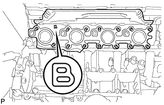
Place a new gasket on the cylinder head with the "B" mark facing the manifold side.
Note
Be careful of the installation direction.
-
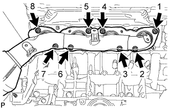
Temporarily install the exhaust manifold, and then uniformly tighten 8 new nuts in several steps, in the sequence shown in the illustration.
- Torque:
- 21 N*m { 214 kgf*cm, 15 ft.*lbf }
-
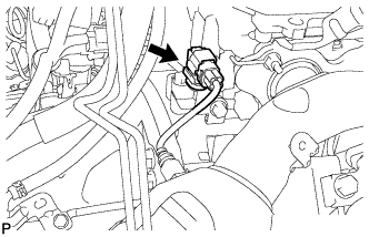
Connect the air fuel ratio sensor connector.
-
-
INSTALL FRONT NO. 1 ENGINE MOUNTING BRACKET LH
-
Install the front No. 1 engine mounting bracket LH with the 5 bolts.
- Torque:
- 35 N*m { 357 kgf*cm, 26 ft.*lbf }
-
-
INSTALL FRONT NO. 1 ENGINE MOUNTING BRACKET RH
-
Install the front No. 1 engine mounting bracket RH with the 5 bolts.
- Torque:
- 35 N*m { 357 kgf*cm, 26 ft.*lbf }
-
-
INSTALL FRONT ENGINE MOUNTING INSULATOR
-
Install the 2 spacers and 2 front engine mounting insulators with the 2 nuts.
- Torque:
- 35 N*m { 357 kgf*cm, 26 ft.*lbf }
-
-
INSTALL NO. 2 EXHAUST MANIFOLD HEAT INSULATOR
-
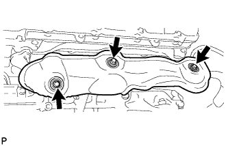
Install the heat insulator with the 3 bolts.
- Torque:
- 10 N*m { 102 kgf*cm, 7 ft.*lbf }
-
-
INSTALL NO. 1 EXHAUST MANIFOLD HEAT INSULATOR
-
Install the heat insulator with the 3 bolts.
- Torque:
- 10 N*m { 102 kgf*cm, 7 ft.*lbf }
-
-
INSTALL OIL LEVEL DIPSTICK GUIDE
-
Apply a light coat of engine oil to a new O-ring.
-
Install the O-ring to the engine oil level dipstick guide.
-
Install the engine oil level dipstick guide with the bolt.
- Torque:
- 10 N*m { 102 kgf*cm, 7 ft.*lbf }
-
Install the engine oil level dipstick.
-
-
INSTALL FRONT FRAME ASSEMBLY
-
Slowly lower the engine and set it to the front frame assembly.
-
Install the 4 nuts.
- Torque:
- 70 N*m { 714 kgf*cm, 52 ft.*lbf }
-
Attach the 2 clips and connect the heater wire connector.
-
-
INSTALL ENGINE AND TRANSMISSION
-
Install the engine and transmission Click here.
-
-
INSPECT AND ADJUST TRANSMISSION FLUID
-
PERFORM RESET MEMORY
Initialize the learned value of RESET MEMORY Click here.