OIL PUMP ASSEMBLY REMOVAL

-
REMOVE LUGGAGE COMPARTMENT MAT SUB-ASSEMBLY (w/ Spare Tire)

-
REMOVE DECK BOARD ASSEMBLY (w/o Spare Tire)

-
REMOVE DECK TRIM SIDE BOARD LH (w/o Spare Tire)
-

Detach the 2 clips and remove the deck trim side board LH.
-
-
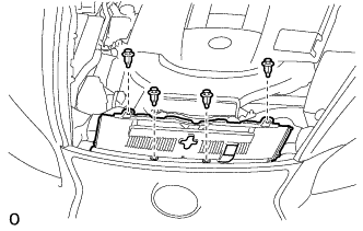
REMOVE BATTERY SERVICE HOLE COVER LH
-

Text in Illustration *A for Standard *B for Ottoman *1 Fastening Tape Detach the clip, fastening tape and remove the battery service hole cover LH.
-
-
PRECAUTION
Note
After turning the power switch off, waiting time may be required before disconnecting the cable from the auxiliary battery terminal. Therefore, make sure to read the disconnecting the cable from the auxiliary battery terminal notice before proceeding with work Click here.
-
DISCONNECT CABLE FROM NEGATIVE BATTERY TERMINAL
Note
When disconnecting the cable, some systems need to be initialized after the cable is reconnected Click here.
-
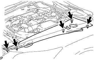
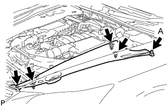
REMOVE V-BANK COVER SUB-ASSEMBLY
-

While using both hands, lift the rear side of the V-bank cover sub-assembly upwards to detach the 4 clips labeled B. Slide the V-bank cover sub-assembly towards the front of the vehicle to detach the 2 clips labeled A, and remove the V-bank cover sub-assembly.
Note
The V-bank cover sub-assembly may be damaged if its front and rear are lifted at the same time.
-
-
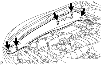
REMOVE AIR CLEANER INLET COVER SUB-ASSEMBLY
-
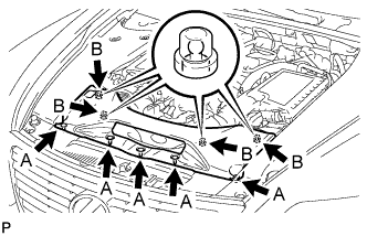
Remove the 5 clips labeled A.
-
Lift up the air cleaner inlet cover sub-assembly to detach the 4 clips labeled B, and remove the air cleaner inlet cover sub-assembly.
-
-
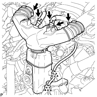
REMOVE NO. 1 AIR CLEANER INLET
-
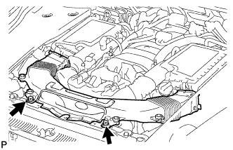
Remove the 2 bolts.
-
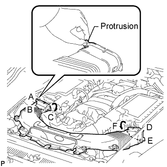
Hold the No. 1 air cleaner inlet by the protrusions labeled A and B, and detach the connections.
-
Rotate the No. 1 air cleaner inlet as shown in the illustration to detach the protrusion labeled C.
-
Hold the No. 1 air cleaner inlet by the protrusions labeled D and E, and detach the connections.
-
Rotate the No. 1 air cleaner inlet as shown in the illustration to detach the protrusion labeled F.
-
-
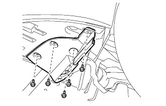
REMOVE ENGINE ROOM SIDE COVER RH
-
for LHD:
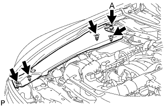
Remove the 5 clips and engine room side cover RH.
Note
Remove the clip labeled A by turning it to prevent the engine room side cover RH and bracket from being damaged.
Tech Tips
The clip labeled A cannot be removed from the engine room side cover RH.
-
for RHD:
Remove the 5 clips and engine room side cover RH.
-
-
REMOVE ENGINE ROOM SIDE COVER LH
-
for LHD:
Remove the 5 clips and engine room side cover LH.
-
for RHD:
Remove the 5 clips and engine room side cover LH.
Note
Remove the clip labeled A by turning it to prevent the engine room side cover LH and bracket from being damaged.
Tech Tips
The clip labeled A cannot be removed from the engine room side cover LH.
-
-
REMOVE COOL AIR INTAKE DUCT SEAL
-
Remove the 4 clips and cool air intake duct seal.
-
-
REMOVE INTAKE AIR CONNECTOR PIPE
-
Disconnect the No. 1 ventilation hose and No. 2 ventilation hose from the intake air connector pipe.
-
Using a clip remover, detach the 2 wire harness clamps.
-
Loosen the 3 hose clamps, and remove the intake air connector pipe.
-
-
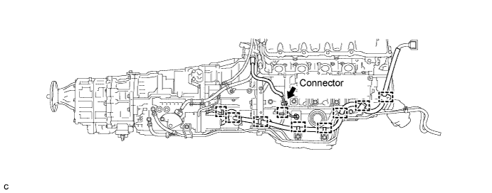
DISCONNECT OIL PUMP MOTOR CONTROLLER CONNECTOR
Note
Be sure to perform the procedure as described below. Do not turn the power switch on (READY) before reconnecting the cable to the negative battery terminal.
-
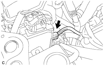
Disconnect the connector from the oil pump motor controller.
-
Applicable period (2007/04 - 2007/12)
-
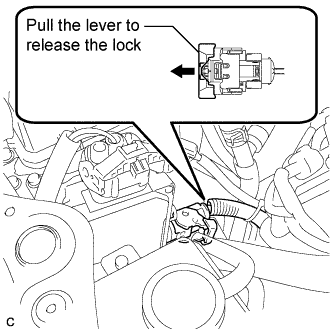
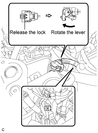
Pull the lever to release the lock on the connector.
-
Release the lock lever on the connector as shown in the illustration. Disconnect the connector from the oil pump motor controller.
Note
When disconnecting the connector, do not apply excessive force to the wire harness.
-
Disconnect the clamp.
Note
When disconnecting the clamp, do not apply excessive force to the wire harness.
-
-
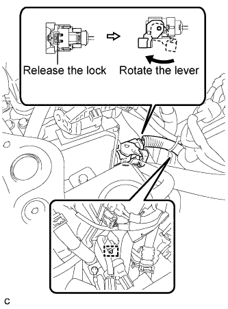
Applicable period (2007/12 -)
-
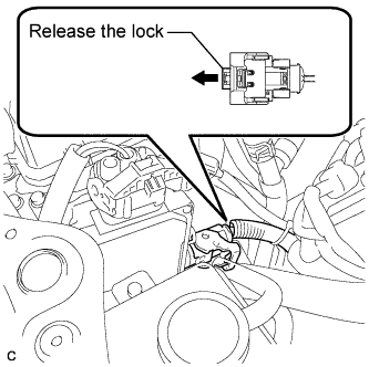
Release the lock on the connector.
-
Release the lock lever on the connector as shown in the illustration. Disconnect the connector from the oil pump motor controller.
Note
When disconnecting the connector, do not apply excessive force to the wire harness.
-
Disconnect the clamp.
Note
When disconnecting the clamp, do not apply excessive force to the wire harness.
-
-
-
REMOVE FRONT CENTER FLOOR COVER (w/ Cover)
-
Remove the 3 screws, 2 bolts, clip and front center floor cover.
-
-
REMOVE NO. 2 ENGINE UNDER COVER
-
Remove the 4 screws, 2 clips and No. 2 engine under cover.
-
-
REMOVE FRONT WHEEL OPENING EXTENSION PAD LH
-
Remove the 5 screws and front wheel opening extension pad LH.
-
-
REMOVE FRONT WHEEL OPENING EXTENSION PAD RH
Tech Tips
Use the same procedure described for the LH side.
-
REMOVE NO. 1 ENGINE UNDER COVER
-
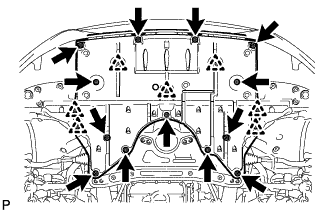
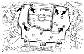
Remove the 13 screws, 7 clips and No. 1 engine under cover.
-
-
REMOVE FRONT LOWER SUSPENSION MEMBER PROTECTOR
-
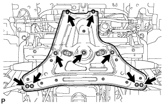
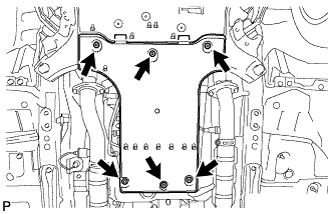
Remove the 9 bolts and front lower suspension member protector.
-
-
DRAIN TRANSMISSION FLUID
-
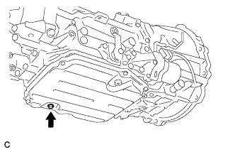
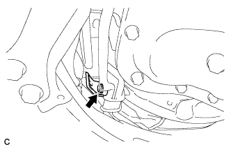
Remove the drain plug and gasket, and drain the ATF.
-
Install a new gasket and the drain plug.
- Torque:
- 20 N*m { 204 kgf*cm, 15 ft.*lbf }
-
-
DRAIN INVERTER COOLANT (for LHD)
Note
-
Do not reuse the drained coolant because it may contain foreign objects.
-
Collect the drained coolant and measure its volume to establish a benchmark. When adding coolant, make sure to add more coolant than the measured amount.
-
Remove the inverter reserve tank cap.
CAUTION:
To avoid the danger of being burned, do not remove the inverter reserve tank cap while the coolant for the inverter is still hot.
Note
Do not remove the plug from the tube.
-
Using a hexagon wrench 10 mm, remove the drain plug indicated in the illustration and drain the coolant.
CAUTION:
Use caution when handling coolant immediately after driving or in summer because it may be hot.
-
Using a hexagon wrench 10 mm, install the drain plug with a new gasket.
- Torque:
- 39 N*m { 400 kgf*cm, 29 ft.*lbf }
-
Measure the volume of the drained coolant.
-
-
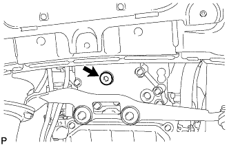
DISCONNECT INLET OIL COOLER HOSE
-
Disconnect the No. 2 oil cooler inlet hose from the radiator assembly.
Note
Place a container under the connection before disconnecting the oil cooler hose because oil in the hose may spill out.
-
-
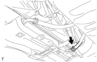
DISCONNECT OUTLET OIL COOLER HOSE
-
Disconnect the No. 2 oil cooler outlet hose from the radiator assembly.
Note
Place a container under the connection before disconnecting the oil cooler hose because oil in the hose may spill out.
-
-
REMOVE NO. 1 EXHAUST PIPE SUPPORT BRACKET SUB-ASSEMBLY
-
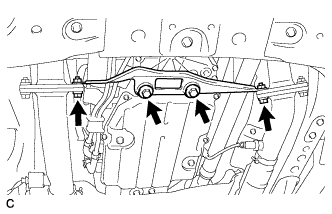
Remove the 2 nuts and 2 bolts from the exhaust manifold LH and RH.
-
Remove the 2 bolts and No. 1 exhaust pipe support bracket sub-assembly.
-
-
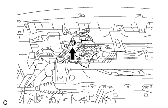
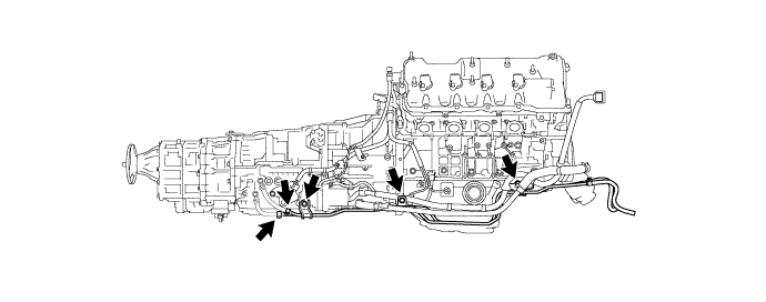
DISCONNECT WIRE HARNESS
-
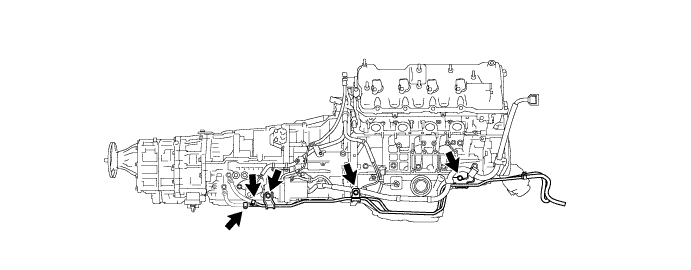
Separate the 9 wire harness clamps and connector from the hybrid vehicle transmission assembly.
-
-
DISCONNECT OUTLET NO. 1 HYBRID WATER PUMP PIPE (for LHD)
-
Remove the clip and disconnect the water pump hose.
-
Remove the 2 bolts and clip, and disconnect the outlet No. 1 hybrid water pump pipe.
-
-
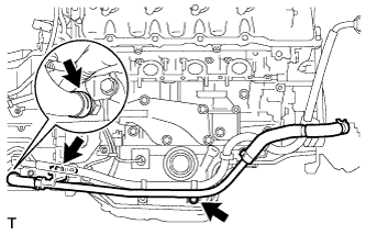
DISCONNECT OIL COOLER TUBE (for LHD)
-
Disconnect the 2 oil cooler hoses.
Note
Do not touch any parts that may be hot, such as the exhaust pipe.
Tech Tips
Cover each disconnected oil cooler hose with a plastic bag or tape to prevent fluid from dripping.
-
Remove the 3 bolts and oil cooler tube.
-
-
DISCONNECT OIL COOLER TUBE (for RHD)
-
Remove the bolt and wire harness clamp bracket.
-
Disconnect the 2 oil cooler hoses.
Note
Do not touch any parts that may be hot, such as the exhaust pipe.
Tech Tips
Cover each disconnected oil cooler hose with a plastic bag or tape to prevent fluid from dripping.
-
Remove the 3 bolts and oil cooler tube.
-
-
REMOVE OIL WITH MOTOR PUMP ASSEMBLY
-
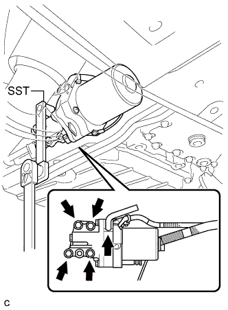
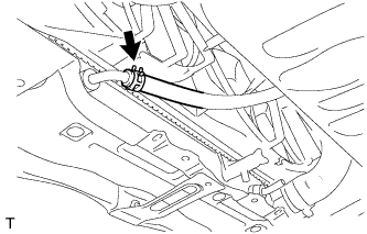
Disconnect the transmission breather hose from the oil with motor pump assembly.
-
Using SST, remove the 4 bolts, oil with motor pump and gasket from the hybrid vehicle transmission assembly.
- SST
- 09961-00950
-