SHIFT LEVER POSITION SENSOR REMOVAL

-
REMOVE LUGGAGE COMPARTMENT MAT SUB-ASSEMBLY (w/ Spare Tire)

-
REMOVE DECK BOARD ASSEMBLY (w/o Spare Tire)

-
REMOVE DECK TRIM SIDE BOARD LH (w/o Spare Tire)
-

Detach the 2 clips and remove the deck trim side board LH.
-
-
REMOVE BATTERY SERVICE HOLE COVER LH
-

Text in Illustration *A for Standard *B for Ottoman *1 Fastening Tape Detach the clip, fastening tape and remove the battery service hole cover LH.
-
-
PRECAUTION
Note
After turning the power switch off, waiting time may be required before disconnecting the cable from the battery terminal. Therefore, make sure to read the disconnecting the cable from the battery terminal notice before proceeding with work Click here.
-
DISCONNECT CABLE FROM NEGATIVE BATTERY TERMINAL
Note
When disconnecting the cable, some systems need to be initialized after the cable is reconnected Click here.
-
REMOVE FRONT CENTER FLOOR COVER (w/ Cover)
-
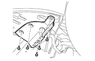
Remove the 3 screws, 2 bolts, clip and front center floor cover.
-
-
REMOVE NO. 2 ENGINE UNDER COVER
-
Remove the 4 screws, 2 clips and No. 2 engine under cover.
-
-
REMOVE FRONT WHEEL OPENING EXTENSION PAD LH
-
Remove the 5 screws and front wheel opening extension pad LH.
-
-
REMOVE FRONT WHEEL OPENING EXTENSION PAD RH
Tech Tips
Use the same procedure described for the LH side.
-
REMOVE NO. 1 ENGINE UNDER COVER
-
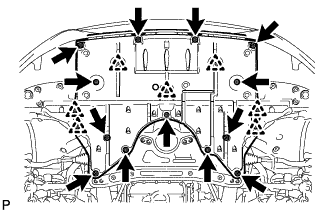
Remove the 13 screws, 7 clips and No. 1 engine under cover.
-
-
REMOVE FRONT LOWER SUSPENSION MEMBER PROTECTOR
-
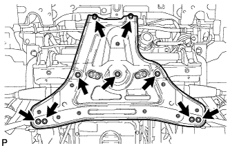
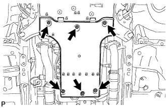
Remove the 9 bolts and front lower suspension member protector.
-
-
SEPARATE OIL COOLER TUBE
-
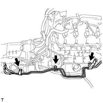
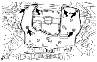
Remove the 3 bolts and separate the oil cooler tube.
-
-
SEPARATE FLOOR SHIFT GEAR SHIFTING ROD SUB-ASSEMBLY
-
Set the shift lever to the neutral position.
-
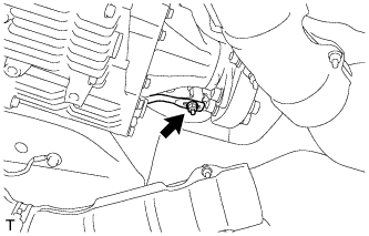
Remove the nut, and separate the floor shift gear shifting rod sub-assembly.
-
-
REMOVE PARK/NEUTRAL POSITION SWITCH
-

Disconnect the park/neutral position switch connector.
-

Remove the nut, washer and transmission control shaft lever.
-
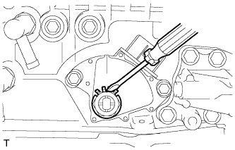
Using a screwdriver, pry out the lock washer.
-
Remove the lock nut and lock washer.
-
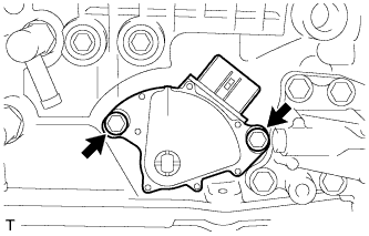
Remove the 2 bolts and park/neutral position switch.
Tech Tips
Make sure that the manual valve lever shaft has not been rotated prior to installing the park/neutral position switch as the detent spring may become detached from the manual valve lever shaft.
-