HV BATTERY INSTALLATION

-
INSTALL NO. 2 HYBRID BATTERY PACK WIRE
CAUTION:
Be sure to wear insulated gloves.
-
Connect the connector.
-
Attach the 5 clamps to install the No. 2 hybrid battery pack wire.
Note
If the wire harness clamp is damaged, replace it with a new one.
-
-
INSTALL BATTERY SMART UNIT
CAUTION:
Be sure to wear insulated gloves.
-
Install the battery smart unit with the nut.
- Torque:
- 7.5 N*m { 76 kgf*cm, 66 in.*lbf }
-
Connect the 3 connectors.
-
-
INSTALL HYBRID BATTERY JUNCTION BLOCK ASSEMBLY
CAUTION:
Be sure to wear insulated gloves.
-
Install the hybrid battery junction block assembly with the 3 nuts.
- Torque:
- 7.5 N*m { 76 kgf*cm, 66 in.*lbf }
-
Connect the 4 connectors.
-
-
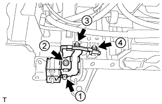
INSTALL HYBRID BATTERY TERMINAL BLOCK
CAUTION:
Be sure to wear insulated gloves.
-
Install the hybrid battery terminal block with the 3 nuts and bolt in the order shown in the illustration.
- Torque:
- for bolt
- 7.5 N*m { 76 kgf*cm, 66 in.*lbf }
- for nut (Except hybrid battery junction block assembly terminal)
- 7.5 N*m { 76 kgf*cm, 66 in.*lbf }
- for nut (Hybrid battery junction block assembly terminal)
- 9.0 N*m { 92 kgf*cm, 80 in.*lbf }
Note
Be sure to follow the order shown when tightening the nuts and bolt.
-
-
INSTALL NO. 4 HYBRID VEHICLE BATTERY SHIELD REINFORCEMENT
CAUTION:
Be sure to wear insulated gloves.
-
Install the No. 4 hybrid vehicle battery shield reinforcement with the 2 nuts.
- Torque:
- 7.5 N*m { 76 kgf*cm, 66 in.*lbf }
-
-
INSTALL POWER STEERING CONVERTER WIRE
CAUTION:
Be sure to wear insulated gloves.
-
Install the power steering converter wire with the nut.
- Torque:
- 7.5 N*m { 76 kgf*cm, 66 in.*lbf }
-
Connect the connector.
-
-
INSTALL NO. 3 HYBRID BATTERY INTAKE DUCT
CAUTION:
Be sure to wear insulated gloves.
-
Install the No. 3 hybrid battery intake duct and connect the intake air temperature sensor.
-
-
INSTALL HV CONVERTER
CAUTION:
Be sure to wear insulated gloves.
-
Install the hybrid vehicle converter with the 4 nuts.
- Torque:
- 7.5 N*m { 76 kgf*cm, 66 in.*lbf }
-
Attach the 4 clamps.
Note
If a wire harness clamp is damaged, replace it with a new one.
-
Connect the 3 connectors.
-
-
INSTALL NO. 2 HYBRID VEHICLE CONVERTER SIGNAL WIRE
CAUTION:
Be sure to wear insulated gloves.
-
Connect the connector to install the No. 2 hybrid vehicle converter signal wire.
-
-
INSTALL CONVERTER COOLING BLOWER BRACKET
CAUTION:
Be sure to wear insulated gloves.
-
Attach the 2 clamps to install the converter cooling blower bracket.
-
-
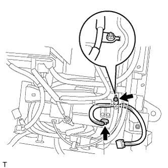
INSTALL HV CONVERTER POWER SUPPLY WIRE
CAUTION:
Be sure to wear insulated gloves.
-
Attach the clamp.
-
Install the hybrid vehicle converter power supply wire with the nut.
- Torque:
- 9.0 N*m { 92 kgf*cm, 80 in.*lbf }
-
-
INSTALL CONVERTER COOLING BLOWER
CAUTION:
Be sure to wear insulated gloves.
-
Attach the 2 claws.
-
Install the converter cooling blower with the 2 nuts and bolt.
- Torque:
- 7.5 N*m { 76 kgf*cm, 66 in.*lbf }
-
Attach the clamp and connect the connector.
-
-
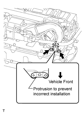
INSTALL CONVERTER WIRE BRACKET
CAUTION:
Be sure to wear insulated gloves.
-
Install the converter wire bracket with the 2 nuts in the direction shown in the illustration.
- Torque:
- 7.5 N*m { 76 kgf*cm, 66 in.*lbf }
-
Attach the clamp.
-
-
INSTALL CONVERTER COOLING EXHAUST DUCT
CAUTION:
Be sure to wear insulated gloves.
-
Attach the clamp and 2 claws to install the converter cooling exhaust duct.
-
Install the clip.
-
-
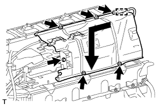
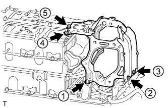
INSTALL NO. 8 HYBRID VEHICLE BATTERY SHIELD SUB-ASSEMBLY
CAUTION:
Be sure to wear insulated gloves.
-
Install the No. 8 hybrid vehicle battery shield sub-assembly as shown in the illustration.
-
Install the 5 nuts and bolt.
- Torque:
- 7.5 N*m { 76 kgf*cm, 66 in.*lbf }
-
Attach the clamp.
-
-
INSTALL NO. 4 HYBRID BATTERY SHIELD PANEL
CAUTION:
Be sure to wear insulated gloves.
-
Install the No. 4 hybrid battery shield panel with the 6 nuts and bolt.
- Torque:
- 7.5 N*m { 76 kgf*cm, 66 in.*lbf }
-
-
INSTALL REAR HYBRID BATTERY WITH LABEL SHIELD
CAUTION:
Be sure to wear insulated gloves.
-
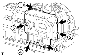
Install the rear hybrid battery with label shield with the 2 nuts and 3 bolts in the order shown in the illustration.
- Torque:
- 7.5 N*m { 76 kgf*cm, 66 in.*lbf }
-
-
INSTALL NO. 1 HYBRID BATTERY INTAKE DUCT
CAUTION:
Be sure to wear insulated gloves.
-
Install the No. 1 hybrid battery intake duct with the 3 clips.
-
-
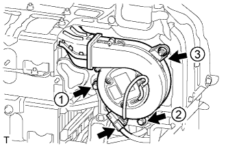
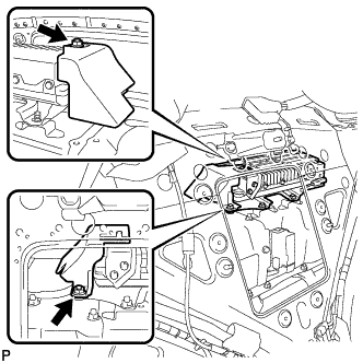
INSTALL BATTERY COOLING BLOWER ASSEMBLY (for Lower Side)
CAUTION:
Be sure to wear insulated gloves.
-
Attach the 2 claws to install the battery cooling blower assembly (for lower side).
-
Install the nut and 2 bolts in the order shown in the illustration.
- Torque:
- 7.5 N*m { 76 kgf*cm, 66 in.*lbf }
-
Connect the connector.
-
Attach the clamp.
-
-
INSTALL NO. 4 HYBRID VEHICLE BATTERY CARRIER BRACKET SUB-ASSEMBLY
CAUTION:
Be sure to wear insulated gloves.
-
Install the No. 4 hybrid vehicle battery carrier bracket sub-assembly with the 4 nuts and 3 bolts.
- Torque:
- 7.5 N*m { 76 kgf*cm, 66 in.*lbf }
-
Install the No. 1 hybrid battery packing as shown in the illustration.
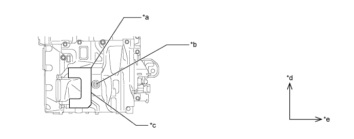
Text in Illustration *a Align with edge of metal plate (reference point) *b Make sure No. 1 hybrid battery packing does not cover bolt *c Align with edge of weld (reference point) *d LH *e FR - -
-
-
INSTALL NO. 1 HYBRID BATTERY SHIELD SUB-ASSEMBLY
CAUTION:
Be sure to wear insulated gloves.
-
Install the No. 1 hybrid battery shield sub-assembly with the 2 nuts.
- Torque:
- 7.5 N*m { 76 kgf*cm, 66 in.*lbf }
-
-
INSTALL NO. 4 HYBRID BATTERY INTAKE DUCT
-
Attach the 2 claws to install the No. 4 hybrid battery intake duct to the battery cooling blower assembly (for upper side).
-
-
INSTALL BATTERY COOLING BLOWER ASSEMBLY (for Upper Side)
CAUTION:
Be sure to wear insulated gloves.
-
Install the battery cooling blower assembly (for upper side) with the nut and 2 bolts in the order shown in the illustration.
- Torque:
- 7.5 N*m { 76 kgf*cm, 66 in.*lbf }
-
Connect the connector.
-
-
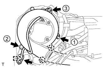
INSTALL NO. 6 HYBRID VEHICLE BATTERY SHIELD SUB-ASSEMBLY
CAUTION:
Be sure to wear insulated gloves.
-
Install the No. 6 hybrid vehicle battery shield sub-assembly with the 3 nuts and 3 bolts in the order shown in the illustration.
- Torque:
- 7.5 N*m { 76 kgf*cm, 66 in.*lbf }
-
-
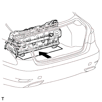
SET HV BATTERY IN VEHICLE
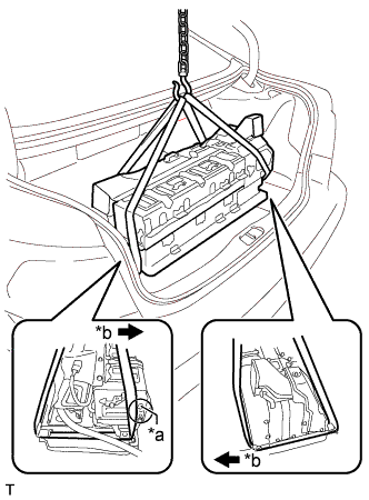
Text in Illustration *a Part A *b Vehicle Rear CAUTION:
Be sure to wear insulated gloves.
-
Place the piece of cardboard in the luggage compartment.
-
Using a rope or equivalent, set the HV battery onto the piece of cardboard.
Note
-
Use cardboard or other similar material to protect the HV battery and vehicle body from damage.
-
In order to prevent the hydrogen hose from being damaged, make sure the rope does not extend toward the rear of the vehicle past the part labeled A when lifting the HV battery.
-
-
-
INSTALL POWER STEERING CONVERTER ASSEMBLY
CAUTION:
Perform work using insulated gloves and insulated tools.
-
Install the 4 nuts and power steering converter assembly.
- Torque:
- 8.0 N*m { 82 kgf*cm, 71 in.*lbf }
-
Connect the 5 connectors.
-
Install the 2 nuts and power steering ECU bracket.
- Torque:
- 8.0 N*m { 82 kgf*cm, 71 in.*lbf }
-
-
INSTALL HV BATTERY
CAUTION:
Be sure to wear insulated gloves.
-
Push the HV battery and piece of cardboard together into the vehicle.
Note
-
When pushing in the HV battery, 2 people are needed. One should work from the luggage compartment side and the other from the cabin side.
-
When pushing in the HV battery, do not allow the wire harnesses and the HV battery case to interfere with the vehicle body.
-
-
Pull out the piece of cardboard and remove it.
-
Temporarily install the 3 bolts for the front part of the HV battery from the cabin side.
-
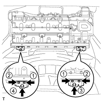
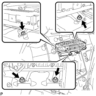
Install the 2 HV battery brackets with the 4 nuts and 2 bolts in the order shown in the illustration.
- Torque:
- for bolt
- 20 N*m { 204 kgf*cm, 15 ft.*lbf }
- for nut
- 7.5 N*m { 76 kgf*cm, 66 in.*lbf }
-
Tighten the 3 bolts for the front part of the HV battery from the cabin side.
- Torque:
- 20 N*m { 204 kgf*cm, 15 ft.*lbf }
-
Remove the luggage compartment mat sub-assembly.
-
w/ Spare Tire:
Take the No. 4 luggage room wire and vehicle wire harness out of the gap, move the spare tire back to its original position and install the bolt.
-
w/o Spare Tire:
Remove the deck board assembly and tool box and take the No. 4 luggage room wire and vehicle wire harness out of the bottom of the luggage compartment.
-
w/ Active Stabilizer Suspension System:
Connect the 2 connectors to the rear active stabilizer control ECU.
-
Install the air conditioning tube assembly to the HV battery with the 2 nuts.
- Torque:
- 9.8 N*m { 100 kgf*cm, 87 in.*lbf }
-
Attach the clamp and connect the No. 2 hybrid battery pack wire.
-
Attach the 4 clamps and install the No. 4 luggage room wire with the 2 nuts.
- Torque:
- 8.0 N*m { 82 kgf*cm, 71 in.*lbf }
-
Remove the 3 nuts holding the fusible link block assembly in place, and then attach the 2 clamps with the fusible link block assembly raised.
-
Connect the 3 connectors.
-
Install the fusible link block assembly with the 3 nuts.
- Torque:
- 8.0 N*m { 82 kgf*cm, 71 in.*lbf }
-
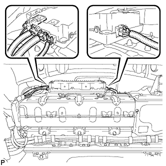
Attach the clamp and connect the 2 connectors.
-
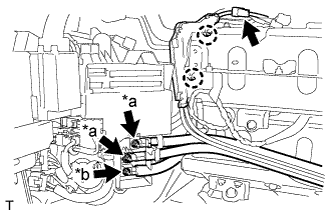
Text in Illustration *a Nut A *b Nut B Install the No. 4 luggage room wire and hybrid vehicle converter power supply wire to the fusible link block assembly with the 3 nuts.
- Torque:
- for nut A
- 12.5 N*m { 127 kgf*cm, 9 ft.*lbf }
- for nut B
- 9.0 N*m { 92 kgf*cm, 80 in.*lbf }
-
Connect the connector.
-
Attach the 2 claws.
-
Attach the 3 claws to install the upper relay block cover.
-
Attach the claw and install the wire harness protector with the 2 nuts.
- Torque:
- 8.0 N*m { 82 kgf*cm, 71 in.*lbf }
-
-
INSTALL SPARE WHEEL GUARD SUB-ASSEMBLY (w/ Spare Tire)
-
Install the spare wheel guard sub-assembly with the 2 clips.
-
-
INSTALL SPARE WHEEL GUARD SUB-ASSEMBLY (w/o Spare Tire)
-
INSTALL TOOL BOX (w/o Spare Tire)
-
Install the tool box with the 2 clips.
-
-
INSTALL LUGGAGE COMPARTMENT MAT SUB-ASSEMBLY (w/o Spare Tire)
-
CONNECT BATTERY ROOM VENTILATION HOSE
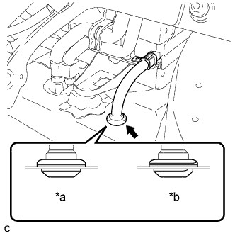
Text in Illustration *a Correct *b Incorrect
-
Connect the battery room ventilation hose to the floor with the grommet.
Note
After installing the grommet, make sure that there is no clearance between the grommet and body.
-
-
CONNECT FRAME WIRE
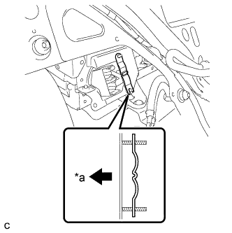
Text in Illustration *a Vehicle Rear CAUTION:
Be sure to wear insulated gloves.
-
Install the battery shield contact as shown in the illustration.
Note
Be sure to install the battery shield contact in the correct direction.
-
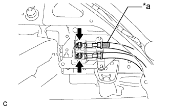
Text in Illustration *a Red Mark Connect the frame wire to the HV battery with the 2 nuts.
- Torque:
- 9.0 N*m { 92 kgf*cm, 80 in.*lbf }
Note
Be sure to align the red mark on the frame wire with the red part of the terminal block.
-
-
INSTALL NO. 2 HYBRID BATTERY SHIELD SUB-ASSEMBLY

Text in Illustration *a Battery Cover Lock Striker *b Push CAUTION:
Be sure to wear insulated gloves.
-
Install the No. 2 hybrid battery shield sub-assembly to the HV battery.
-
Install the No. 2 hybrid battery shield sub-assembly with the 2 nuts in the order shown in the illustration.
- Torque:
- 8.0 N*m { 82 kgf*cm, 71 in.*lbf }
-
Install the battery cover lock striker and push the button.
-
-
INSTALL HOLE PLUG
-
Install the 2 hole plugs.
-
-
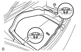
INSTALL REAR SEAT CONSOLE BOX LOWER BRACKET
-
Install the rear seat console box lower bracket with the 6 bolts.
- Torque:
- 7.5 N*m { 76 kgf*cm, 66 in.*lbf }
-
-
INSTALL NO. 2 CENTER FLOOR TO BRACE EXTENSION
-
Install the No. 2 center floor to brace extension with the 3 clips.
-
-
INSTALL NO. 1 CENTER FLOOR TO BRACE EXTENSION
-
Install the No. 1 center floor to brace extension with the 3 clips.
-
-
INSTALL REAR COOLER UNIT (w/ Rear Air Conditioning System)
-
INSTALL REAR COOLER UNIT (w/o Rear Air Conditioning System)
-
INSTALL REAR SEAT ASSEMBLY (for Fixed Seat Type)
-
INSTALL REAR SEAT ASSEMBLY (for Power Seat)
-
INSTALL REAR SEAT ASSEMBLY (for Ottoman)
-
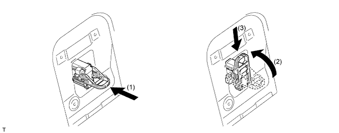
INSTALL SERVICE PLUG GRIP
CAUTION:
Be sure to wear insulated gloves.
-
Wear insulated gloves and insert the service plug grip.
-
Turn the lever of the service plug grip 90° and slide the service plug grip downward until a click sound is heard.
-
-
INSTALL SERVICE PLUG COVER
-
Install the service plug cover with the 4 bolts.
- Torque:
- 7.5 N*m { 76 kgf*cm, 66 in.*lbf }
-
-
INSTALL REAR SEAT LOWER CONSOLE BOX COVER (for 4-Passenger with Ottoman)
-
Attach the 2 hooks and 4 claws to install the rear seat lower console box cover.
-
-
INSTALL ARMREST DOOR CAP (except 4-Passenger with Ottoman)
-
Attach the 2 hooks and 6 claws to install the armrest door cap.
-
-
CONNECT CABLE TO BATTERY TERMINAL
Note
When disconnecting the cable some systems need to be initialized after the cable is reconnected Click here.
-
INSTALL BATTERY SERVICE HOLE COVER LH
-

Text in Illustration *A for Standard *B for Ottoman Attach the battery service hole cover LH with the clip and fastening tape.
-
-
INSTALL DECK TRIM SIDE BOARD LH (w/o Spare Tire)
-

Attach the 2 clips to install the deck trim side board LH.
-
-
INSTALL DECK BOARD ASSEMBLY (w/o Spare Tire)

-
INSTALL LUGGAGE COMPARTMENT MAT SUB-ASSEMBLY (w/ Spare Tire)

-
CHECK SRS WARNING LIGHT