OIL PUMP MOTOR CONTROLLER INSTALLATION

-
INSTALL OIL PUMP MOTOR CONTROLLER
CAUTION:
Be sure to perform the procedure as described below. Do not turn the power switch on (READY) before reconnecting the cable to the negative battery terminal.
-
Install the oil pump motor controller with the 3 bolts.
- Torque:
- 6.0 N*m { 61 kgf*cm, 53 in.*lbf }
-
Install the clamp to the bracket.
-
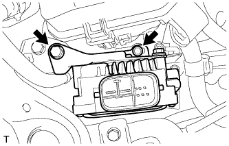
Install the oil pump motor controller with bracket with the 2 bolts.
- Torque:
- 5.0 N*m { 51 kgf*cm, 44 in.*lbf }
-
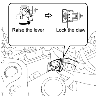
Connect the connector and securely lock the lock lever as shown in the illustration.
Note
-
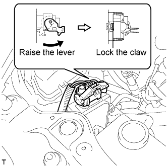
Be sure to securely lock the claw on the connector.
-
Push the connector all the way in and lock the lock lever.
Tech Tips
When the connector is pushed all the way in, the lock lever will move slightly to the lock position.
-
-
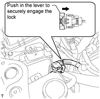
Push in the lever to securely engage the lock on the connector.
-
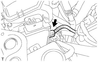
Connect the connector to the oil pump motor controller.
-
Connect the connector and securely lock the lock lever as shown in the illustration.
Note
-
Be sure to securely lock the claw on the connector.
-
Push the connector all the way in and lock the lock lever.
Tech Tips
When the connector is pushed all the way in, the lock lever will move slightly to the lock position.
-
-
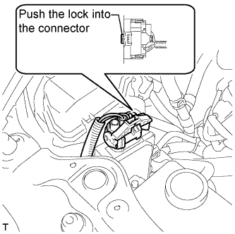
Push the lock into the lock lever to securely lock the lock lever on the connector.
-
-
INSTALL NO. 1 AIR CLEANER INLET
-
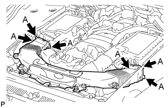
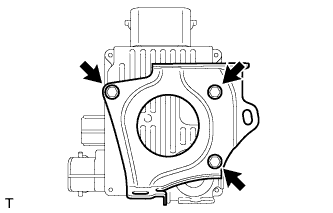
Align the holes with the connection areas labeled A, and attach the No. 1 air cleaner inlet.
-
Install the No. 1 air cleaner inlet with the 2 bolts.
- Torque:
- 5.0 N*m { 51 kgf*cm, 44 in.*lbf }
-
-
INSTALL AIR CLEANER INLET COVER SUB-ASSEMBLY
-
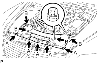
Attach the 4 clips labeled B.
Note
-
Make sure the clips are attached securely.
-
Attaching the clips forcefully or hitting the top of the clips may damage them.
-
-
Install the air cleaner inlet cover sub-assembly with the 5 clips labeled A.
-
-
INSTALL ENGINE ROOM SIDE COVER RH
-
Install the engine room side cover RH with the 5 clips.
-
-
INSTALL V-BANK COVER SUB-ASSEMBLY
-

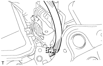
After sliding the V-bank cover sub-assembly from the vehicle front to the rear to attach the 2 clips labeled A, attach the 4 clips labeled B and install the V-bank cover sub-assembly.
CAUTION:
-
Make sure the clips are attached securely.
-
Attaching the clips forcefully or hitting the top of the clips may damage them.
-
-
-
CONNECT CABLE TO AUXILIARY BATTERY NEGATIVE TERMINAL
Note
When disconnecting the cable, some systems need to be initialized after the cable is reconnected Click here.
-
INSTALL BATTERY SERVICE HOLE COVER LH
-

Text in Illustration *A for Standard *B for Ottoman Attach the battery service hole cover LH with the clip and fastening tape.
-
-
INSTALL DECK TRIM SIDE BOARD LH (w/o Spare Tire)
-

Attach the 2 clips to install the deck trim side board LH.
-
-
INSTALL DECK BOARD ASSEMBLY (w/o Spare Tire)

-
INSTALL LUGGAGE COMPARTMENT MAT SUB-ASSEMBLY (w/ Spare Tire)
