SHIFT LEVER POSITION SENSOR INSTALLATION

-
INSTALL PARK/NEUTRAL POSITION SWITCH
Tech Tips
Make sure that the manual valve lever shaft has not been rotated prior to installing the park/neutral position switch as the detent spring may become detached from the manual valve lever shaft.
-
Install the park/neutral position switch to the hybrid vehicle transmission assembly.
-
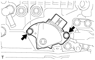
Temporarily install the 2 bolts.
Tech Tips
Fully tighten the bolts with the neutral alignment mark line aligned with the groove. [*1]
-

Install a new lock washer and the nut.
- Torque:
- 6.9 N*m { 70 kgf*cm, 61 in.*lbf }
-

Temporarily install the control shaft lever.
Tech Tips
Bend the tabs of the lock washer before fully tightening the nut. [*2]
-

Turn the control shaft lever counterclockwise until it stops. Next, turn the control shaft lever clockwise 2 notches to set it to the N position.
-
Remove the transmission control shaft lever.
-

Align the neutral alignment mark line with the switch groove, and tighten the 2 adjusting bolts. [*1]
- Torque:
- 5.4 N*m { 55 kgf*cm, 48 in.*lbf }
-
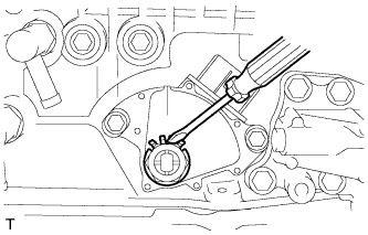
Using a screwdriver, bend the tabs of the lock washer.
Note
Make sure that the nut is held firmly.
-
Install the transmission control shaft lever with the nut. [*2]
- Torque:
- 16 N*m { 163 kgf*cm, 12 ft.*lbf }
-

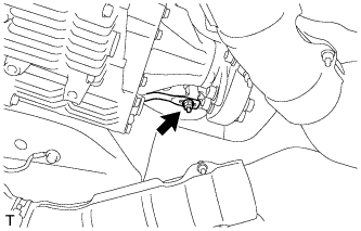
Connect the park/neutral position switch connector.
-
-
INSTALL FLOOR SHIFT GEAR SHIFTING ROD SUB-ASSEMBLY
-
Move the shift lever to the N position and tighten the nut while lightly pushing the lever toward the R position.
- Torque:
- 13 N*m { 130 kgf*cm, 9 ft.*lbf }
Note
Do not push the shift lever too hard.
-
-
INSTALL OIL COOLER TUBE
-
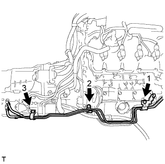
Install the oil cooler tube with the 3 bolts in the order shown in the illustration.
- Torque:
- 12 N*m { 122 kgf*cm, 9 ft.*lbf }
-
-
CONNECT CABLE TO AUXILIARY BATTERY NEGATIVE TERMINAL
Note
When disconnecting the cable, some systems need to be initialized after the cable is reconnected Click here.
-
INSPECT SHIFT LEVER POSITION
-
Remove the nut, and disconnect the floor shift gear shifting rod sub-assembly.
-
Turn the control shaft lever counterclockwise until it stops. Next, turn the control shaft lever clockwise 2 notches to set it to the N position.
-
Move the shift lever to the N position and tighten the nut while lightly pushing the shift lever toward the R position.
- Torque:
- 13 N*m { 130 kgf*cm, 9 ft.*lbf }
Note
Do not push the shift lever too hard.
-
Check that the shift lever moves smoothly and the shift lever and gear operate correctly.
-
-
INSPECT PARK/NEUTRAL POSITION SWITCH POSITION
-
Apply the parking brake.
-
Chock the wheels to secure the vehicle.
-
Turn the power switch on (READY).
-
Move the shift lever to the D position and release the brake pedal.
Note
Be sure to apply the parking brake and chock the wheels to secure the vehicle.
-
Slowly move the shift lever to the N position and measure moving distance (A) of the shift lever from the original point to the gear activation point.
Note
Be sure to move the shift lever slowly.
-
Move the shift lever to the R position and release the brake pedal.
Note
Be sure to apply the parking brake and chock the wheels to secure the vehicle.
-
Slowly move the shift lever to the N position and measure moving distance (B) of the shift lever from the original point to the gear activation point.
Note
Be sure to move the shift lever slowly.
-
Check that moving distances (A) and (B) shown in the illustration are almost the same.

Tech Tips
-
If moving distances (A) and (B) are almost the same, adjustment of the shift lever position is not necessary.
-
If moving distance (A) is shorter than (B), perform adjustment of the shift lever position [*1].
-
If moving distance (B) is shorter than (A), perform adjustment of the shift lever position [*2].
-
-
-
ADJUST PARK/NEUTRAL POSITION SWITCH POSITION
-
If moving distance (A) is shorter than (B) [*1]:

Tech Tips
When the shift lever is moved from the R to N position, the moving distance of the shift lever from the original point to the gear activation point becomes longer.
-
Move the shift lever to the N position.
-

Loosen the 2 bolts.
-
Slightly turn the park/neutral position switch clockwise.
-
Tighten the park/neutral position switch with the 2 bolts.
- Torque:
- 5.4 N*m { 55 kgf*cm, 48 in.*lbf }
-
Recheck the shift lever position.
-
-
If moving distance (B) is shorter than (A) [*2]:

Tech Tips
If the shift lever is moved from the D to N position, the moving distance of the shift lever from the original point to the gear activation point becomes longer.
-
Move the shift lever to the N position.
-
Loosen the 2 bolts.
-
Slightly turn the park/neutral position switch counterclockwise.
-
Tighten the park/neutral position switch with the 2 bolts.
- Torque:
- 5.4 N*m { 55 kgf*cm, 48 in.*lbf }
-
Recheck the shift lever position sensor position.
-
-
-
INSPECT SHIFT LEVER OPERATION
-
While moving the shift lever from the N position to each position, check that the lever moves smoothly and that the shift position indicator comes on properly according to the shift lever position.
-
Turn the power switch on (READY) and check the following:
-
When the shift lever is moved to the D position, the vehicle moves forward.
-
When the shift lever is moved to the R position, the buzzer sounds and the vehicle moves in reverse.
Note
The vehicle should not move when the shift position indicator is off.
-
-
-
INSTALL FRONT LOWER SUSPENSION MEMBER PROTECTOR
-

Install the front lower suspension member protector with the 9 bolts.
- Torque:
- for bolt A
- 20 N*m { 204 kgf*cm, 15 ft.*lbf }
- except bolt A
- 58 N*m { 593 kgf*cm, 43 ft.*lbf }
-
-
INSTALL NO. 1 ENGINE UNDER COVER
-
Install the No. 1 engine under cover with the 13 screws and 7 clips.
-
-
INSTALL FRONT WHEEL OPENING EXTENSION PAD RH
Tech Tips
Use the same procedure described for the LH side.
-
INSTALL FRONT WHEEL OPENING EXTENSION PAD LH
-
Install the front wheel opening extension pad LH with the 5 screws.
-
-
INSTALL NO. 2 ENGINE UNDER COVER
-
Install the No. 2 engine under cover with the 4 screws and 2 clips.
-
-
INSTALL FRONT CENTER FLOOR COVER (w/ Cover)
-
Install the front center floor cover with the 3 screws, 2 bolts and clip.
- Torque:
- 5.4 N*m { 55 kgf*cm, 48 in.*lbf }
-
-
INSTALL BATTERY SERVICE HOLE COVER LH
-

Text in Illustration *A for Standard *B for Ottoman Attach the battery service hole cover LH with the clip and fastening tape.
-
-
INSTALL DECK TRIM SIDE BOARD LH (w/o Spare Tire)
-

Attach the 2 clips to install the deck trim side board LH.
-
-
INSTALL DECK BOARD ASSEMBLY (w/o Spare Tire)

-
INSTALL LUGGAGE COMPARTMENT MAT SUB-ASSEMBLY (w/ Spare Tire)
