HYBRID BATTERY SYSTEM, Diagnostic DTC:P0ABF-123, P0AC1-123, P0AC2-123

| DTC Code | DTC Name |
|---|---|
| P0ABF-123 | Hybrid Battery Pack Current Sensor Circuit |
| P0AC1-123 | Hybrid Battery Pack Current Sensor "A" Circuit Low |
| P0AC2-123 | Hybrid Battery Pack Current Sensor "A" Circuit High |
DESCRIPTION
-
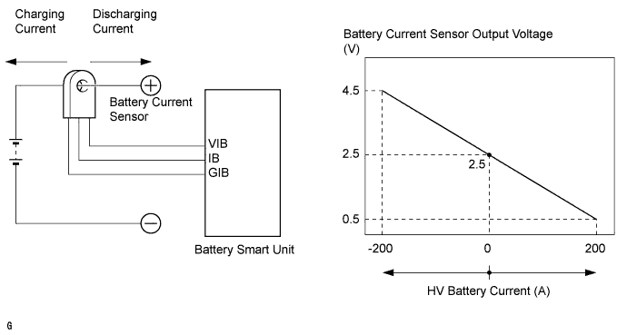
The battery current sensor, which is located in the HV battery junction block assembly on the positive side of the HV battery, detects the amperage that flows to and from the HV battery. The battery smart unit receives a voltage of between 0 and 5 V that is in proportion to the amperage flowing in the cable. This voltage goes into the IB terminal from the battery current sensor. A battery current sensor output voltage below 2.5 V indicates that the HV battery is being discharged, and a voltage above 2.5 V indicates that the HV battery is being charged. The hybrid vehicle control ECU determines the amount of either charge or discharge amperage of the HV battery based on the signals that are input to terminal IB of the battery smart unit from the battery current sensor. The hybrid vehicle control ECU also calculates the SOC (state of charge) of the HV battery based on the accumulated amperage.
| DTC Code | DTC Detection Condition | Trouble Area |
|---|---|---|
| P0ABF-123 P0AC1-123 P0AC2-123 |
When the battery current sensor is abnormal (1 trip detection) |
|
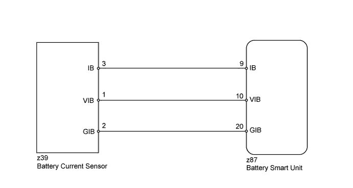
WIRING DIAGRAM
INSPECTION PROCEDURE
CAUTION:
-
Before inspecting the high-voltage system, take safety precautions such as wearing insulated gloves and removing the service plug grip to prevent electrical shocks. After removing the service plug grip, put it in your pocket to prevent other technicians from accidentally reconnecting it while you are working on the high-voltage system.
-
After disconnecting the service plug grip, wait for at least 10 minutes before touching any of the high-voltage connectors or terminals. After waiting for 10 minutes, check the voltage at the terminals in the inspection point in the inverter with converter assembly. The voltage should be 0 V before beginning work.
Tech Tips
Waiting for at least 10 minutes is required to discharge the high-voltage capacitor inside the inverter with converter assembly.
PROCEDURE
-
CHECK FOR DTCS (DTC P0AFC-123 IS OUTPUT)
-
Connect the intelligent tester to the DLC3.
-
Turn the power switch on (IG).
-
Select the following menu items: Powertrain / Hybrid Control / Trouble Codes.
-
Check if DTCs are output.
Result Result Proceed to P0AFC-123 is not output. A P0AFC-123 is output. B
B 
GO TO DTC (P0AFC-123) Click here
A 
-
-
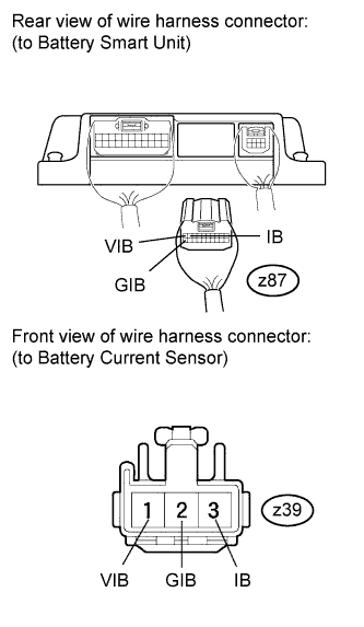
CHECK HARNESS AND CONNECTOR (BATTERY SMART UNIT - BATTERY CURRENT SENSOR)
CAUTION:
Be sure to wear insulated gloves.
-
Remove the HV battery Click here.
-
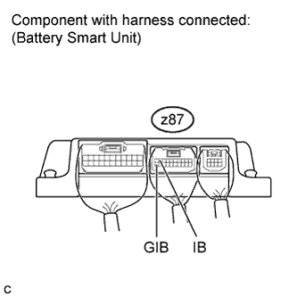
Disconnect the z87 battery smart unit connector.
Tech Tips
For the removal and installation procedures related to the battery smart unit connector inspection, Click here.
-
Disconnect the z39 HV battery junction block assembly (battery current sensor) connector.
Tech Tips
For the removal and installation procedures related to the HV battery junction block assembly (battery current sensor) connector inspection, Click here.
-
Measure the resistance according to the value(s) in the table below.
Standard Resistance (Check for open) Tester Connection Condition Specified Condition z87-9 (IB) - z39-3 (IB) Always Below 1 Ω z87-20 (GIB) - z39-2 (GIB) Always Below 1 Ω z87-10 (VIB) - z39-1 (VIB) Always Below 1 Ω Standard Resistance (Check for short) Tester Connection Condition Specified Condition z87-9 (IB) or z39-3 (IB) - Body ground and other terminals Always 10 kΩ or higher z87-20 (GIB) or z39-2 (GIB) - Body ground and other terminals Always 10 kΩ or higher z87-10 (VIB) or z39-1 (VIB) - Body ground and other terminals Always 10 kΩ or higher -
Reconnect the z87 battery smart unit connector.
-
Reconnect the z39 HV battery junction block assembly (battery current sensor) connector.
NG
REPAIR OR REPLACE HARNESS OR CONNECTOR
OK
-
-
CHECK BATTERY SMART UNIT (VIB VOLTAGE)
CAUTION:
Be sure to wear insulated gloves.
-
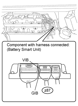
Place the HV battery in the vehicle so that measurements can be made at the battery smart unit connector.
Note
Make sure all the covers are installed to the HV battery when placing it in the vehicle, and then remove the covers again after the HV battery is in place.
Tech Tips
-
Follow the installation procedures to the point where the HV battery is set in the vehicle Click here.
-
Do not install the service plug grip.
-
-
Reconnect all the connectors that were disconnected when the HV battery was removed.
-
Turn the power switch on (IG).
-
Measure the voltage according to the value(s) in the table below.
Standard Voltage Tester Connection Switch Condition Specified Condition z87-10 (VIB) - z87-20 (GIB) Power switch on (IG) 4.6 to 5.4 V Tech Tips
If the power switch is turned on (IG) with the service plug grip removed, DTC P0A0D-350 for the interlock switch system will be set. If this DTC is output, clear the DTC using the intelligent tester Click here.
NG
REPLACE BATTERY SMART UNIT Click here
OK
-
-
CHECK BATTERY SMART UNIT (BATTERY CURRENT SENSOR VOLTAGE)
CAUTION:
Be sure to wear insulated gloves.
-
Turn the power switch on (IG).
-
Measure the voltage according to the value(s) in the table below.
Standard Voltage Tester Connection Switch Condition Specified Condition z87-9 (IB) - z87-20 (GIB) Power switch on (IG) 2.46 to 2.54 V Tech Tips
If the power switch is turned on (IG) with the service plug grip removed, DTC P0A0D-350 for the interlock switch system will be set. If this DTC is output, clear the DTC using the intelligent tester Click here.
NG
REPLACE HV BATTERY JUNCTION BLOCK ASSEMBLY Click here
OK 
REPLACE BATTERY SMART UNIT Click here
-