HYBRID BATTERY SYSTEM, Diagnostic DTC:P0A9D-123, P0A9E-123, P0AC7-123, P0AC8-123, P0ACC-123, P0ACD-123, P0AEA-123, P0AEB-123, P0BC4-123, P0BC5-123, P0C35-123, P0C36-123

| DTC Code | DTC Name |
|---|---|
| P0A9D-123 | Hybrid Battery Temperature Sensor "A" Circuit Low |
| P0A9E-123 | Hybrid Battery Temperature Sensor "A" Circuit High |
| P0AC7-123 | Hybrid Battery Temperature Sensor "B" Circuit Low |
| P0AC8-123 | Hybrid Battery Temperature Sensor "B" Circuit High |
| P0ACC-123 | Hybrid Battery Temperature Sensor "C" Circuit Low |
| P0ACD-123 | Hybrid Battery Temperature Sensor "C" Circuit High |
| P0AEA-123 | Hybrid Battery Temperature Sensor "D" Circuit Low |
| P0AEB-123 | Hybrid Battery Temperature Sensor "D" Circuit High |
| P0BC4-123 | Hybrid Battery Temperature Sensor "E" Circuit Low |
| P0BC5-123 | Hybrid Battery Temperature Sensor "E" Circuit High |
| P0C35-123 | Hybrid Battery Temperature Sensor "F" Circuit Low |
| P0C36-123 | Hybrid Battery Temperature Sensor "F" Circuit High |
DESCRIPTION
-
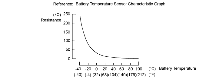
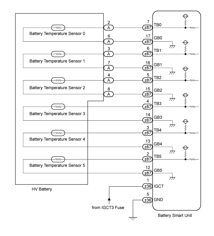
The battery temperature sensors are installed to the HV battery in 6 locations: 3 at the bottom of the upper part of the HV battery and 3 at the bottom of the lower part of the HV battery. The resistance value of the thermistor built into each battery temperature sensor varies in accordance with changes in HV battery temperature. As the HV battery temperature decreases, the thermistor resistance value increases. Conversely, as the HV battery temperature increases, the thermistor resistance value decreases. The battery smart unit uses the battery temperature sensors to detect the HV battery temperature and sends the detected value to the hybrid vehicle control ECU. Based on these detection results, the hybrid vehicle control ECU controls the battery cooling blower assembly and rear cooling unit (the battery cooling blower assembly starts operating when the HV battery temperature rises above a certain level).
| DTC Code | DTC Detection Condition | Trouble Area |
|---|---|---|
| P0A9D-123 | The temperature detected by battery temperature sensor 0 is 95°C (203°F) or more (short to GND). (1 trip detection) |
|
| P0A9E-123 | The temperature detected by battery temperature sensor 0 is -45°C (-49°F) or less (open circuit or short to +B). (1 trip detection) | |
| P0AC7-123 | The temperature detected by battery temperature sensor 1 is 95°C (203°F) or more (short to GND). (1 trip detection) | |
| P0AC8-123 | The temperature detected by battery temperature sensor 1 is -45°C (-49°F) or less (open circuit or short to +B). (1 trip detection) | |
| P0ACC-123 | The temperature detected by battery temperature sensor 2 is 95°C (203°F) or more (short to GND). (1 trip detection) | |
| P0ACD-123 | The temperature detected by battery temperature sensor 2 is -45°C (-49°F) or less (open circuit or short to +B). (1 trip detection) | |
| P0AEA-123 | The temperature detected by battery temperature sensor 3 is 95°C (203°F) or more (short to GND). (1 trip detection) | |
| P0AEB-123 | The temperature detected by battery temperature sensor 3 is -45°C (-49°F) or less (open circuit or short to +B). (1 trip detection) | |
| P0BC4-123 | The temperature detected by battery temperature sensor 4 is 95°C (203°F) or more (short to GND). (1 trip detection) | |
| P0BC5-123 | The temperature detected by battery temperature sensor 4 is -45°C (-49°F) or less (open circuit or short to +B). (1 trip detection) | |
| P0C35-123 | The temperature detected by battery temperature sensor 5 is 95°C (203°F) or more (short to GND). (1 trip detection) | |
| P0C36-123 | The temperature detected by battery temperature sensor 5 is -45°C (-49°F) or less (open circuit or short to +B). (1 trip detection) |
Tech Tips
After confirming that DTC P0A9D-123, P0A9E-123, P0AC7-123, P0AC8-123, P0ACC-123, P0ACD-123, P0AEA-123, P0AEB-123, P0BC4-123, P0BC5-123, P0C35-123 and P0C36-123 are output, use the intelligent tester to check "Temp of Batt TB 1 to 6" in the hybrid control system data list.
| Displayed Temperature | Malfunction |
|---|---|
| -45°C (-49°F) or less | Open circuit or short to +B |
| 95°C (203°F) or higher | Short to GND |
INSPECTION PROCEDURE
CAUTION:
-
Before inspecting the high-voltage system, take safety precautions such as wearing insulated gloves and removing the service plug grip to prevent electrical shocks. After removing the service plug grip, put it in your pocket to prevent other technicians from accidentally reconnecting it while you are working on the high-voltage system.
-
After disconnecting the service plug grip, wait for at least 10 minutes before touching any of the high-voltage connectors or terminals. After waiting for 10 minutes, check the voltage at the terminals in the inspection point in the inverter with converter assembly. The voltage should be 0 V before beginning work.
Tech Tips
Waiting for at least 10 minutes is required to discharge the high-voltage capacitor inside the inverter with converter assembly.
PROCEDURE
-
CHECK FOR DTCS (DTC P0AFC-123 IS OUTPUT)
-
Connect the intelligent tester to the DLC3.
-
Turn the power switch on (IG).
-
Select the following menu items: Powertrain / Hybrid Control / Trouble Codes.
-
Check if DTCs are output.
Result Result Proceed to P0AFC-123 is not output. A P0AFC-123 is output. B
B 
GO TO DTC (P0AFC-123) Click here
A 
-
-
READ VALUE USING INTELLIGENT TESTER
-
Select the following menu items: Powertrain / Hybrid Control / Data List / Temp of Batt TB 1 to 6.
Tech Tips
"Temp of Batt TB 1 to 6" in the Data List represents battery temperature sensors 0 to 5.
-
Read the data list.
Tech Tips
Compare each of the 6 battery temperature sensor values to determine which battery temperature sensor (0 to 5) is malfunctioning.
NEXT
-
-
CHECK CONNECTOR CONNECTION CONDITION (BATTERY TEMPERATURE SENSOR)
-
Remove the HV battery Click here.
-
Check the connection of the battery temperature sensor connector (intermediate connector).
OK The connector is connected securely and there are no contact problems.
NG
CONNECT SECURELY
OK
-
-
CHECK CONNECTOR CONNECTION CONDITION (BATTERY SMART UNIT)
CAUTION:
Be sure to wear insulated gloves.
-
Check the connection of connector z87 of the battery smart unit.
OK The connector is connected securely and there are no contact problems. Tech Tips
For the removal and installation procedures related to the battery smart unit connector inspection, Click here.
NG
CONNECT SECURELY
OK
-
-
CHECK HV BATTERY (BATTERY TEMPERATURE SENSOR)
CAUTION:
Be sure to wear insulated gloves.
-
Disconnect the z87 battery smart unit connector.
Tech Tips
For the removal and installation procedures related to the battery smart unit connector inspection, Click here.
-
For the malfunctioning battery temperature sensor(s), measure the resistance according to the value(s) in the table below.
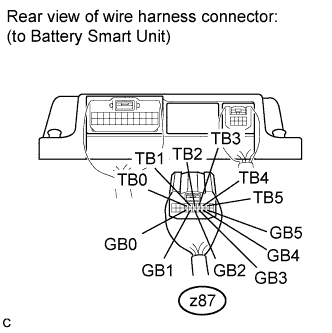
Standard Resistance (Battery temperature sensor 0) Tester Connection Condition Specified Condition z87-7 (TB0) - z87-17 (GB0) Thermistor temperature: 0°C (32°F) 27.3 to 28.4 kΩ z87-7 (TB0) - z87-17 (GB0) Thermistor temperature: 25°C (77°F) 9.9 to 10.1 kΩ z87-7 (TB0) - z87-17 (GB0) Thermistor temperature: 40°C (104°F) 5.72 to 5.90 kΩ Standard Resistance (Battery temperature sensor 1) Tester Connection Condition Specified Condition z87-6 (TB1) - z87-16 (GB1) Thermistor temperature: 0°C (32°F) 27.3 to 28.4 kΩ z87-6 (TB1) - z87-16 (GB1) Thermistor temperature: 25°C (77°F) 9.9 to 10.1 kΩ z87-6 (TB1) - z87-16 (GB1) Thermistor temperature: 40°C (104°F) 5.72 to 5.90 kΩ Standard Resistance (Battery temperature sensor 2) Tester Connection Condition Specified Condition z87-5 (TB2) - z87-15 (GB2) Thermistor temperature: 0°C (32°F) 27.3 to 28.4 kΩ z87-5 (TB2) - z87-15 (GB2) Thermistor temperature: 25°C (77°F) 9.9 to 10.1 kΩ z87-5 (TB2) - z87-15 (GB2) Thermistor temperature: 40°C (104°F) 5.72 to 5.90 kΩ Standard Resistance (Battery temperature sensor 3) Tester Connection Condition Specified Condition z87-4 (TB3) - z87-14 (GB3) Thermistor temperature: 0°C (32°F) 27.3 to 28.4 kΩ z87-4 (TB3) - z87-14 (GB3) Thermistor temperature: 25°C (77°F) 9.9 to 10.1 kΩ z87-4 (TB3) - z87-14 (GB3) Thermistor temperature: 40°C (104°F) 5.72 to 5.90 kΩ Standard Resistance (Battery temperature sensor 4) Tester Connection Condition Specified Condition z87-3 (TB4) - z87-13 (GB4) Thermistor temperature: 0°C (32°F) 27.3 to 28.4 kΩ z87-3 (TB4) - z87-13 (GB4) Thermistor temperature: 25°C (77°F) 9.9 to 10.1 kΩ z87-3 (TB4) - z87-13 (GB4) Thermistor temperature: 40°C (104°F) 5.72 to 5.90 kΩ Standard Resistance (Battery temperature sensor 5) Tester Connection Condition Specified Condition z87-2 (TB5) - z87-12 (GB5) Thermistor temperature: 0°C (32°F) 27.3 to 28.4 kΩ z87-2 (TB5) - z87-12 (GB5) Thermistor temperature: 25°C (77°F) 9.9 to 10.1 kΩ z87-2 (TB5) - z87-12 (GB5) Thermistor temperature: 40°C (104°F) 5.72 to 5.90 kΩ -
Disconnect the z36 battery smart unit connector.
-
Measure the resistance according to the value(s) in the table below.
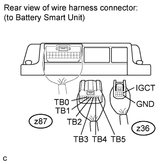
Standard Resistance Tester Connection Condition Specified Condition z87-7 (TB0) - z36-1 (IGCT) Always 10 kΩ or higher z87-7 (TB0) - z36-5 (GND) Always 10 kΩ or higher z87-6 (TB1) - z36-1 (IGCT) Always 10 kΩ or higher z87-6 (TB1) - z36-5 (GND) Always 10 kΩ or higher z87-5 (TB2) - z36-1 (IGCT) Always 10 kΩ or higher z87-5 (TB2) - z36-5 (GND) Always 10 kΩ or higher z87-4 (TB3) - z36-1 (IGCT) Always 10 kΩ or higher z87-4 (TB3) - z36-5 (GND) Always 10 kΩ or higher z87-3 (TB4) - z36-1 (IGCT) Always 10 kΩ or higher z87-3 (TB4) - z36-5 (GND) Always 10 kΩ or higher z87-2 (TB5) - z36-1 (IGCT) Always 10 kΩ or higher z87-2 (TB5) - z36-5 (GND) Always 10 kΩ or higher -
Measure the resistance according to the value(s) in the table below.
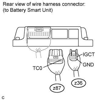
Standard Resistance Tester Connection Condition Specified Condition z87-1 (TC0) - z36-1 (IGCT) Always 10 kΩ or higher z87-1 (TC0) - z36-5 (GND) Always 10 kΩ or higher Result Result Proceed to OK A NG (When inspecting for malfunctions of battery temperature sensors 0 to 2) B NG (When inspecting for malfunctions of battery temperature sensors 3 to 5) C
B 
CHECK HARNESS AND CONNECTOR (BATTERY SMART UNIT - INTAKE AIR TEMPERATURE SENSOR) Click here
C
REPLACE HV BATTERY Click here
A 
REPLACE BATTERY SMART UNIT Click here
-
-
CHECK HARNESS AND CONNECTOR (BATTERY SMART UNIT - INTAKE AIR TEMPERATURE SENSOR)
-
Disconnect the A battery temperature sensor connector (intermediate connector).
-
Measure the resistance according to the value(s) in the table below.
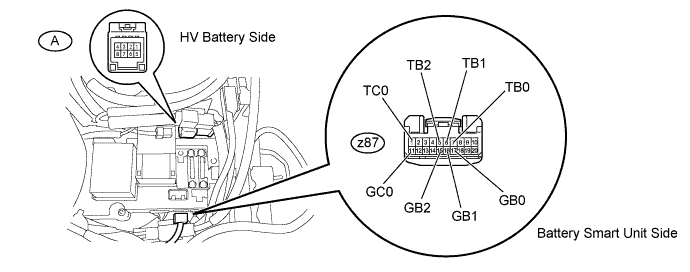
Standard Resistance Tester Connection Condition Specified Condition z87-7 (TB0) - A-2 Always Below 1 Ω z87-6 (TB1) - A-3 Always Below 1 Ω z87-5 (TB2) - A-4 Always Below 1 Ω z87-1 (TC0) - A-1 Always Below 1 Ω z87- 17 (GB0) - A-6 Always Below 1 Ω z87-16 (GB1) - A-7 Always Below 1 Ω z87-15 (GB2) - A-8 Always Below 1 Ω z87-11 (GC0) - A-5 Always Below 1 Ω Standard Resistance Tester Connection Condition Specified Condition z87-7 (TB0) - Body ground and other terminals Always 10 kΩ or higher z87-6 (TB1) - Body ground and other terminals Always 10 kΩ or higher z87-5 (TB2) - Body ground and other terminals Always 10 kΩ or higher z87-1 (TC0) - Body ground and other terminals Always 10 kΩ or higher
NG
REPAIR OR REPLACE HARNESS OR CONNECTOR
OK
REPLACE HV BATTERY Click here
-