HV BATTERY REMOVAL

-
READ OUTPUT DTC
-
Check for DTCs Click here.
Note
Confirm that P0AA6 (Hybrid Battery Voltage System Isolation Fault) is not output before performing removal or installation work on the internal parts of the battery. If the DTC is output, perform troubleshooting procedures first.
-
-
REMOVE LUGGAGE COMPARTMENT MAT SUB-ASSEMBLY (w/ Spare Tire)

-
REMOVE DECK BOARD ASSEMBLY (w/o Spare Tire)

-
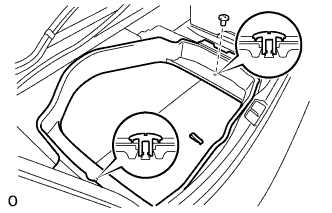
REMOVE DECK TRIM SIDE BOARD LH (w/o Spare Tire)
-

Detach the 2 clips and remove the deck trim side board LH.
-
-
REMOVE BATTERY SERVICE HOLE COVER LH
-

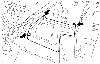
Text in Illustration *A for Standard *B for Ottoman *1 Fastening Tape Detach the clip, fastening tape and remove the battery service hole cover LH.
-
-
PRECAUTION
Note
After turning the power switch off, waiting time may be required before disconnecting the cable from the auxiliary battery negative (-) terminal. Therefore, make sure to read the disconnecting the cable from the auxiliary battery negative (-) terminal notices before proceeding with work Click here.
-
DISCONNECT AUXILIARY BATTERY TERMINAL
Note
When disconnecting the cable, some systems need to be initialized after the cable is reconnected Click here.
Tech Tips
Both cables should be disconnected to prevent the AMD terminal from shorting to ground.
-
REMOVE REAR SEAT LOWER CONSOLE BOX COVER (for 4-Passenger with Ottoman)
-
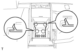
Using a screwdriver, detach the 4 claws, then detach the 2 hooks and remove the rear seat lower console box cover.
Tech Tips
Tape the screwdriver tip before use.
-
-
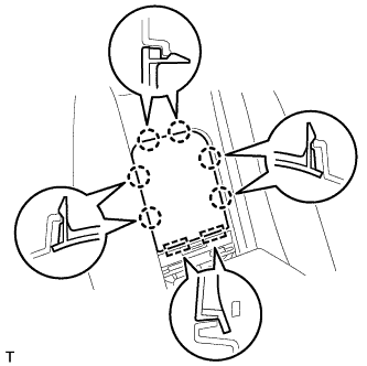
REMOVE ARMREST DOOR CAP (except 4-Passenger with Ottoman)
-
Using a thin-bladed screwdriver, detach the 6 claws.
Tech Tips
Tape the screwdriver tip before use.
-
Detach the 2 hooks and remove the armrest door cap.
-
-
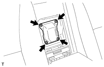
REMOVE SERVICE PLUG COVER
-
Remove the 4 bolts and service plug cover.
-
-
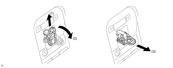
REMOVE SERVICE PLUG GRIP
CAUTION:
-
Remove the service plug grip to interrupt a high voltage circuit at the time of the check.
-
Keep the removed service plug grip in your pocket to prevent other technicians from accidentally reconnecting it while you are servicing the vehicle.
-
All the high voltage wiring connectors are orange colored.
-
Wear insulated gloves. Slide the service plug grip upward, turn the lever downward, and then remove the service plug grip.
CAUTION:
After disconnecting the service plug grip, wait for at least 10 minutes before touching any of the high-voltage connectors or terminals.
Note
Never turn the power switch on (READY) with the service plug grip removed as malfunctions may occur.
Tech Tips
Waiting for at least 10 minutes is required to discharge the high-voltage capacitor inside the inverter with converter assembly.
-
-
REMOVE COWL TOP VENTILATOR LOUVER RH (for LHD)
-
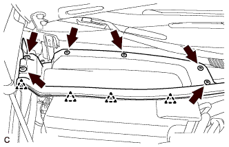
Remove the 4 clips and hood to cowl top seal.
-
Remove the 6 clips and cowl top ventilator louver RH.
-
-
REMOVE COWL TOP VENTILATOR LOUVER LH (for RHD)
-
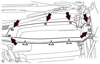
Remove the 4 clips and hood to cowl top seal.
-
Remove the 6 clips and cowl top ventilator louver LH.
-
-
REMOVE MOTOR CABLE COVER RH (for LHD)
-
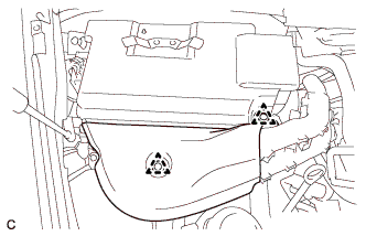
Remove the 2 clips and motor cable cover RH.
-
-
REMOVE MOTOR CABLE COVER LH (for RHD)
-
Remove the 2 clips and motor cable cover LH.
-
-
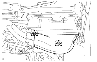
REMOVE INVERTER COVER ASSEMBLY RH (for LHD)
-
Remove the 2 clips and inverter cover assembly RH.
-
-
REMOVE INVERTER COVER ASSEMBLY LH (for RHD)
-
Remove the 2 clips and inverter cover assembly LH.
-
-
REMOVE CONNECTOR COVER ASSEMBLY (for LHD)
CAUTION:
Wear insulating gloves.
-
Using an insulated tool, remove the 2 bolts and connector cover assembly.
Note
-
Cover the hole where the cable was connected with tape or equivalent (non-residue type) to prevent entry of foreign matter.
-
Do not touch the high voltage connectors or terminals for 10 minutes after the service plug grip is removed.
-
-
-
REMOVE CONNECTOR COVER ASSEMBLY (for RHD)
CAUTION:
Wear insulating gloves.
-
Using an insulated tool, remove the 2 bolts and connector cover assembly.
Note
-
Cover the hole where the cable was connected with tape or equivalent (non-residue type) to prevent entry of foreign matter.
-
Do not touch the high voltage connectors or terminals for 10 minutes after the service plug grip is removed.
-
-
-
CHECK TERMINAL VOLTAGE (for LHD)
CAUTION:
Wear insulating gloves.
-
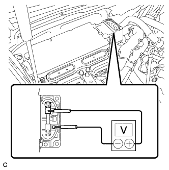
Using the voltmeter, measure the voltage between the terminals of the 2 phase connectors.
Standard voltage 0 V Tech Tips
Use measuring range of DC 750 V or more on the voltmeter.
-
-
CHECK TERMINAL VOLTAGE (for RHD)
CAUTION:
Wear insulating gloves.
-
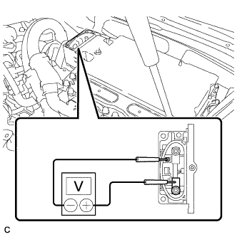
Using the voltmeter, measure the voltage between the terminals of the 2 phase connectors.
Standard voltage 0 V Tech Tips
Use measuring range of DC 750 V or more on the voltmeter.
-
-
INSTALL CONNECTOR COVER ASSEMBLY (for LHD)
CAUTION:
Wear insulating gloves.
-
Using an insulated tool, install the connector cover assembly with the 2 bolts.
- Torque:
- 8.0 N*m { 82 kgf*cm, 71 in.*lbf }
-
-
INSTALL CONNECTOR COVER ASSEMBLY (for RHD)
CAUTION:
Wear insulating gloves.
-
Using an insulated tool, install the connector cover assembly with the 2 bolts.
- Torque:
- 8.0 N*m { 82 kgf*cm, 71 in.*lbf }
-
-
INSTALL INVERTER COVER ASSEMBLY RH (for LHD)
-
Align the locating hole of the inverter cover assembly RH with the locating pin of the inverter with converter assembly. Set the inverter cover assembly RH to the inverter with converter assembly.
-
Press the positions where the clips are to secure the inverter cover assembly RH to the inverter with converter assembly.
-
-
INSTALL INVERTER COVER ASSEMBLY LH (for RHD)
-
Align the locating hole of the inverter cover assembly LH with the locating pin of the inverter with converter assembly. Set the inverter cover assembly LH to the inverter with converter assembly.
-
Press the positions where the clips are to secure the inverter cover assembly LH to the inverter with converter assembly.
-
-
INSTALL MOTOR CABLE COVER RH (for LHD)
-
Install the motor cable cover RH with the 2 clips.
-
-
INSTALL MOTOR CABLE COVER LH (for RHD)
-
Install the motor cable cover LH with the 2 clips.
-
-
INSTALL COWL TOP VENTILATOR LOUVER RH (for LHD)
-
Install the hood to cowl top seal with the 4 clips.
-
Install the cowl top ventilator louver RH with the 6 clips.
-
-
INSTALL COWL TOP VENTILATOR LOUVER LH (for RHD)
-
Install the hood to cowl top seal with the 4 clips.
-
Install the cowl top ventilator louver LH with the 6 clips.
-
-
REMOVE REAR SEAT ASSEMBLY (for Fixed Seat Type)
-
REMOVE REAR SEAT ASSEMBLY (for Power Seat)
-
REMOVE REAR SEAT ASSEMBLY (for Ottoman)
-
REMOVE REAR COOLER UNIT (w/ Rear Air Conditioning System)
-
REMOVE REAR COOLER UNIT (w/o Rear Air Conditioning System)
-
REMOVE NO. 1 CENTER FLOOR TO BRACE EXTENSION
-
Remove the 3 clips and No. 1 center floor to brace extension.
-
-
REMOVE NO. 2 CENTER FLOOR TO BRACE EXTENSION
-
Remove the 3 clips and No. 2 center floor to brace extension.
-
-
REMOVE REAR SEAT CONSOLE BOX LOWER BRACKET
-
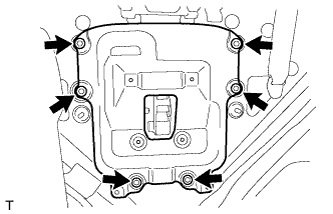
Remove the 6 bolts and rear seat console box lower bracket.
-
-
REMOVE HOLE PLUG
-
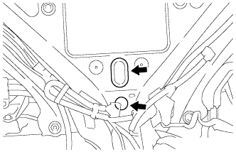
Remove the 2 hole plugs.
-
-
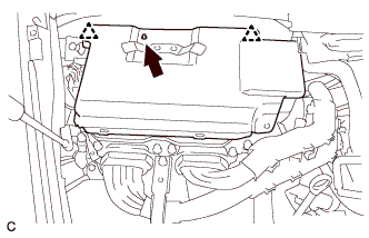
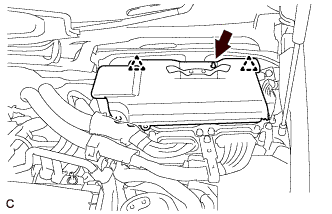
REMOVE NO. 2 HYBRID BATTERY SHIELD SUB-ASSEMBLY
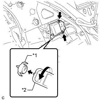
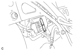
Text in Illustration *1 Battery Cover Lock Striker *2 Service Plug Grip CAUTION:
Be sure to wear insulated gloves.
-
Using the service plug grip, release the battery cover lock striker.
-
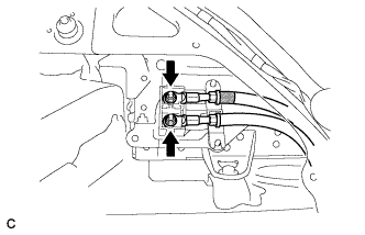
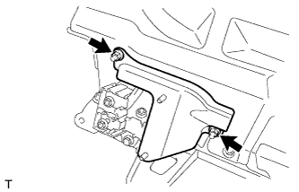
Remove the 2 nuts and disconnect the No. 2 HV battery shield sub-assembly from the HV battery.
-
-
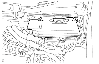
DISCONNECT FRAME WIRE
CAUTION:
Be sure to wear insulated gloves.
-
Remove the 2 nuts and disconnect the frame wire from the HV battery.
Note
Insulate the terminals of the removed high voltage wire with insulating tape.
-
Remove the battery shield contact from the HV battery.
-
-
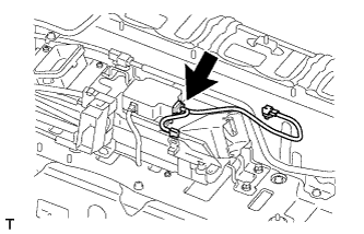
REMOVE BATTERY ROOM VENTILATION HOSE
-
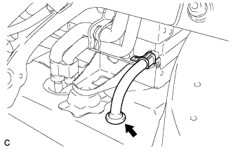
Remove the grommet and battery room ventilation hose from the floor.
-
-
REMOVE LUGGAGE COMPARTMENT MAT SUB-ASSEMBLY (w/o Spare Tire)
-
REMOVE TOOL BOX (w/o Spare Tire)
-
Remove the 2 clips and tool box.
-
-
REMOVE SPARE WHEEL GUARD SUB-ASSEMBLY (w/ Spare Tire)
-
Remove the 2 clips and spare wheel guard sub-assembly.
-
-
REMOVE SPARE WHEEL GUARD SUB-ASSEMBLY (w/o Spare Tire)
-
DISCONNECT HV BATTERY
CAUTION:
Be sure to wear insulated gloves.
-
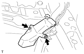
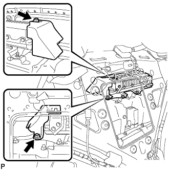
Remove the 2 nuts.
-
Detach the claw and remove the wire harness protector.
-
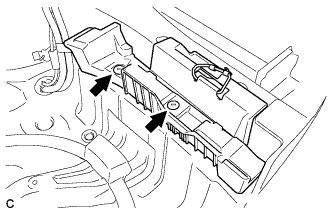
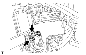
Detach the 3 claws and remove the upper relay block cover.
-
Detach the 2 claws and disconnect the connector.
-
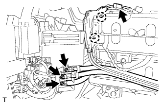
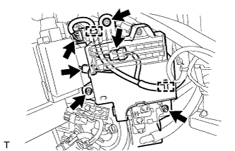
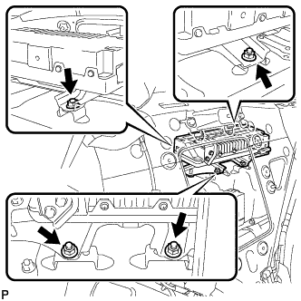
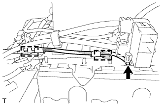
Remove the 3 nuts and disconnect the No. 4 luggage room wire and hybrid vehicle converter power supply wire from the fusible link block assembly.
Note
Insulate the terminals of the removed wire with insulating tape to prevent a short to body ground.
-
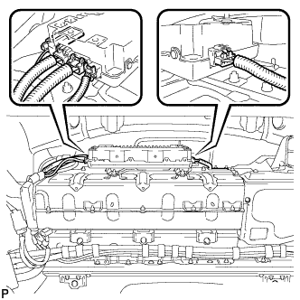
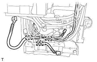
Disconnect the 2 connectors and detach the clamp.
-
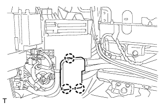
Remove the 3 nuts, and then detach the 2 clamps with the fusible link block assembly raised.
-
Disconnect the 3 connectors.
Tech Tips
After performing the step above, temporarily install the fusible link block assembly with the 3 nuts so that the HV battery can be removed easily.
-
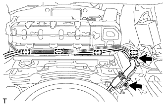
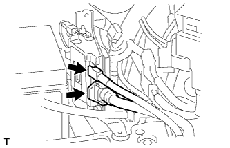
Remove the 2 nuts, detach the 4 clamps and disconnect the No. 4 luggage room wire.
-
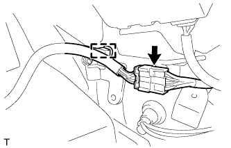
Detach the clamp and disconnect the No. 2 hybrid battery pack wire connector.
-
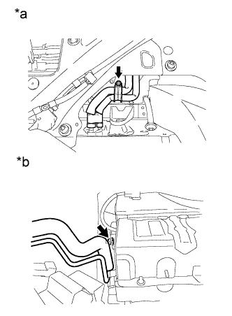
Text in Illustration *a Cabin Side *b Luggage Compartment Side Remove the 2 nuts and disconnect the air conditioning tube assembly from the HV battery.
-
w/ Active Stabilizer Suspension System:
Disconnect the 2 connectors.
-
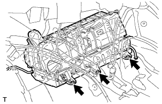
Remove the 3 bolts for the front part of the HV battery from the cabin side.
-
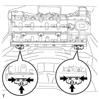
Remove the 4 nuts, 2 bolts and 2 HV battery brackets.
-
w/ Spare Tire:
Remove the bolt that holds the spare tire in place, move the spare tire and set the No. 4 luggage room wire and vehicle wire harness into the gap left by the spare tire.
-
w/o Spare Tire:
Place the No. 4 luggage room wire and vehicle wire harness in the bottom of the luggage compartment and install the tool box and deck board assembly.
Note
Be careful not to damage the No. 4 luggage room wire or vehicle wire harness.
-
Install the luggage compartment floor mat upside down.
-
Prepare a piece of cardboard that is at least 780 mm (2.56 ft.) long and 540 mm (1.77 ft.) wide.
-
Lift the HV battery alternating between the left and right sides and place it on the piece of cardboard.
-
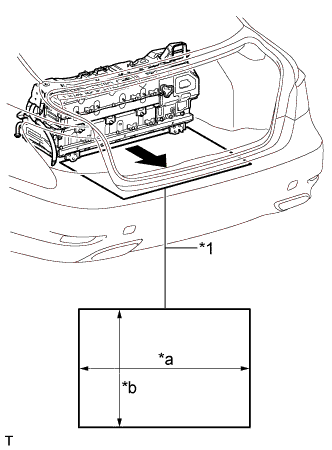
Text in Illustration *1 Cardboard *a 780 mm (2.56 ft.) *b 540 mm (1.77 ft.) Pull out the HV battery and piece of cardboard together from the rear of the vehicle.
Note
-
When pulling out the HV battery assembly, 2 people are needed. One should work from the luggage compartment side and the other from the cabin side.
-
When pulling out the HV battery assembly, do not allow the wire harnesses and the HV battery assembly case to interfere with the vehicle body.
-
-
-
REMOVE POWER STEERING CONVERTER ASSEMBLY
CAUTION:
Perform work using insulated gloves and insulated tools.
-
Remove the 2 nuts and power steering ECU bracket.
-
Disconnect the 5 connectors.
-
Remove the 4 nuts and power steering converter assembly.
-
-
REMOVE HV BATTERY
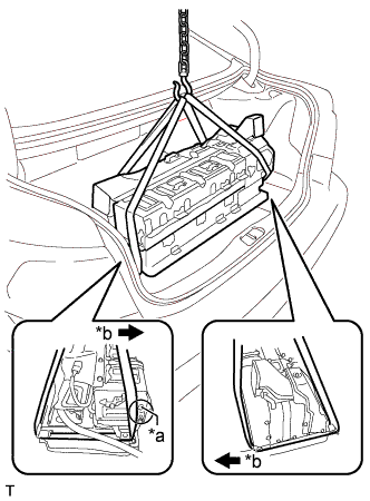
Text in Illustration *a Part A *b Vehicle Rear CAUTION:
Be sure to wear insulated gloves.
-
Using a rope or equivalent, remove the HV battery from the vehicle.
Note
-
Use cardboard or other similar material to protect the HV battery and vehicle body from damage.
-
In order to prevent the hydrogen hose from being damaged, make sure the rope does not extend toward the rear of the vehicle past the part labeled A when lifting the HV battery.
-
-
-
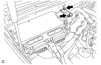
REMOVE NO. 6 HYBRID VEHICLE BATTERY SHIELD SUB-ASSEMBLY
CAUTION:
Be sure to wear insulated gloves.
-
Remove the 3 nuts, 3 bolts and No. 6 hybrid vehicle battery shield sub-assembly.
-
-
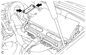
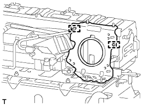
REMOVE BATTERY COOLING BLOWER ASSEMBLY (for Upper Side)
CAUTION:
Be sure to wear insulating gloves.
-
Disconnect the connector.
-
Remove the nut, 2 bolts and battery cooling blower assembly (for upper side).
-
-
REMOVE NO. 4 HYBRID BATTERY INTAKE DUCT
CAUTION:
Be sure to wear insulating gloves.
-
Detach the 2 claws and remove the No. 4 hybrid battery intake duct from the battery cooling blower assembly (for upper side).
-
-
REMOVE NO. 1 HYBRID BATTERY SHIELD SUB-ASSEMBLY
CAUTION:
Be sure to wear insulated gloves.
-
Remove the 2 nuts and No. 1 hybrid battery shield sub-assembly.
-
-
REMOVE NO. 4 HYBRID VEHICLE BATTERY CARRIER BRACKET SUB-ASSEMBLY
CAUTION:
Be sure to wear insulated gloves.
-
Remove the No. 1 hybrid battery packing.
-
Remove the 4 nuts, 3 bolts and No. 4 hybrid vehicle battery carrier bracket sub-assembly.
-
-
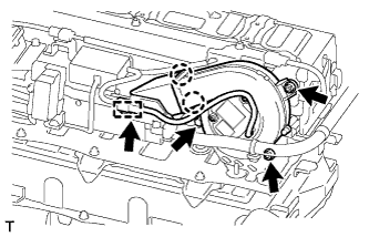
REMOVE BATTERY COOLING BLOWER ASSEMBLY (for Lower Side)
CAUTION:
Be sure to wear insulating gloves.
-
Detach the clamp and disconnect the connector.
-
Remove the nut and 2 bolts.
-
Detach the 2 claws and remove the battery cooling blower assembly (for lower side).
-
-
REMOVE NO. 1 HYBRID BATTERY INTAKE DUCT
CAUTION:
Be sure to wear insulated gloves.
-
Remove the 3 clips and No. 1 hybrid battery intake duct.
-
-
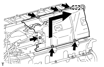
REMOVE REAR HYBRID BATTERY WITH LABEL SHIELD
CAUTION:
Be sure to wear insulated gloves.
-
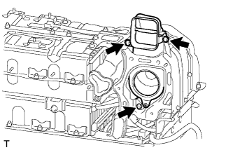
Remove the 2 nuts, 3 bolts and rear hybrid battery with label shield.
-
-
REMOVE NO. 4 HYBRID BATTERY SHIELD PANEL
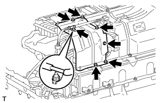
CAUTION:
Be sure to wear insulated gloves.
-
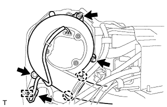
Remove the 6 nuts, bolt and No. 4 hybrid battery shield panel.
-
-
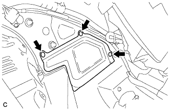
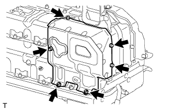
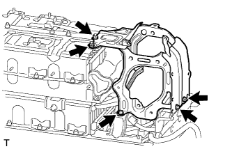
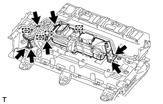
REMOVE NO. 8 HYBRID VEHICLE BATTERY SHIELD SUB-ASSEMBLY
CAUTION:
Be sure to wear insulated gloves.
-
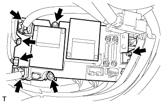
Detach the clamp.
-
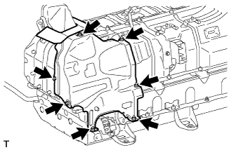
Remove the 5 nuts, bolt and No. 8 hybrid vehicle battery shield sub-assembly as shown in the illustration.
-
-
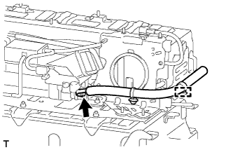
REMOVE CONVERTER COOLING EXHAUST DUCT
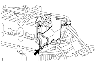
CAUTION:
Be sure to wear insulated gloves.
-
Remove the clip.
-
Detach the clamp and 2 claws and remove the converter cooling exhaust duct.
-
-
REMOVE CONVERTER WIRE BRACKET
CAUTION:
Be sure to wear insulated gloves.
-
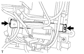
Detach the clamp.
-
Remove the 2 nuts and converter wire bracket.
-
-
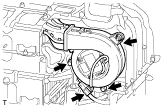
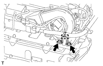
REMOVE CONVERTER COOLING BLOWER
CAUTION:
Be sure to wear insulated gloves.
-
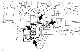
Detach the clamp and disconnect the connector.
-
Remove the 2 nuts and bolt.
-
Detach the 2 claws and remove the converter cooling blower.
-
-
REMOVE HV CONVERTER POWER SUPPLY WIRE
CAUTION:
Be sure to wear insulated gloves.
-
Detach the clamp.
-
Remove the nut and hybrid vehicle converter power supply wire.
-
-
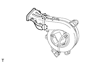
REMOVE CONVERTER COOLING BLOWER BRACKET
CAUTION:
Be sure to wear insulated gloves.
-
Detach the 2 clamps and remove the converter cooling blower bracket.
-
-
REMOVE NO. 2 HYBRID VEHICLE CONVERTER SIGNAL WIRE
CAUTION:
Be sure to wear insulated gloves.
-
Disconnect the connector and remove the No. 2 hybrid vehicle converter signal wire.
-
-
REMOVE HV CONVERTER
CAUTION:
Be sure to wear insulated gloves.
-
Disconnect the 3 connectors.
-
Detach the 4 clamps.
-
Remove the 4 nuts and hybrid vehicle converter.
-
-
REMOVE NO. 3 HYBRID BATTERY INTAKE DUCT
CAUTION:
Be sure to wear insulated gloves.
-
Disconnect the intake air temperature sensor and remove the No. 3 hybrid battery intake duct.
-
-
REMOVE POWER STEERING CONVERTER WIRE
CAUTION:
Be sure to wear insulated gloves.
-
Disconnect the connector.
-
Remove the nut and power steering converter wire.
-
-
REMOVE NO. 4 HYBRID VEHICLE BATTERY SHIELD REINFORCEMENT
CAUTION:
Be sure to wear insulated gloves.
-
Remove the 2 nuts and No. 4 hybrid vehicle shield reinforcement.
-
-
REMOVE HYBRID BATTERY TERMINAL BLOCK
CAUTION:
Be sure to wear insulated gloves.
-
Remove the 3 nuts, bolt and hybrid battery terminal block.
-
-
REMOVE HYBRID BATTERY JUNCTION BLOCK ASSEMBLY
CAUTION:
Be sure to wear insulated gloves.
-
Disconnect the 4 connectors.
-
Remove the 3 nuts and hybrid battery junction block assembly.
Note
Insulate the connectors of the removed high voltage wires with insulating tape.
-
-
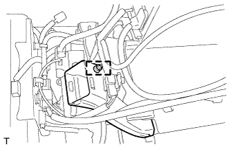
REMOVE BATTERY SMART UNIT
CAUTION:
Be sure to wear insulated gloves.
-
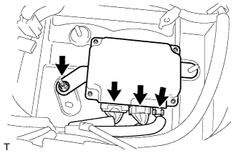
Disconnect the 3 connectors from the battery smart unit.
-
Remove the nut and battery smart unit.
Note
Insulate the connectors of the removed high voltage wires with insulating tape.
-
-
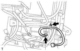
REMOVE NO. 2 HYBRID BATTERY PACK WIRE
CAUTION:
Be sure to wear insulated gloves.
-
Detach the 2 clamps and disconnect the connector.
-
Detach the 3 clamps and remove the No. 2 hybrid battery pack wire.
-