HYBRID BATTERY SYSTEM, Diagnostic DTC:P0A97-123

| DTC Code | DTC Name |
|---|---|
| P0A97-123 | Hybrid Battery Pack Cooling Fan 2 Performance / Stuck OFF |
DESCRIPTION
Refer to the description for DTC P0A99-123 Click here.
| DTC Code | DTC Detection Condition | Trouble Area |
|---|---|---|
| P0A97-123 |
|
|
WIRING DIAGRAM
Refer to the wiring diagram for DTC P0A99-123 Click here.
INSPECTION PROCEDURE
PROCEDURE
-
CHECK FOR DTCS (DTC P0AFC-123 IS OUTPUT)
-
Connect the intelligent tester to the DLC3.
-
Turn the power switch on (IG).
-
Select the following menu items: Powertrain / Hybrid Control / Trouble Codes.
-
Check if DTCs are output.
Result Result Proceed to P0AFC-123 is not output A P0AFC-123 is output. B
B 
GO TO DTC (P0AFC-123) Click here
A 
-
-
CHECK REAR COOLING UNIT
-
Inspect rear air conditioning blower operation. (w/ Rear Cooler)
-
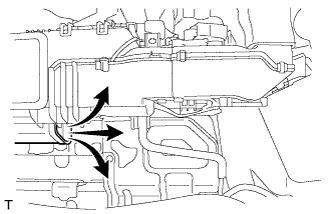
Remove the air duct RH.
Tech Tips
For the removal and installation procedures related to the air duct RH, Click here.
-
Check if cool air comes out from the hole shown in the illustration when the rear air conditioning blower is operated using the rear air conditioning control panel.
OK Cool air comes out.
-
-
Inspect rear air conditioning blower operation. (w/o Rear Cooler)
-
Connect the intelligent tester to the DLC3.
-
Turn the power switch on (IG).
-
Select the following menu items: Body / Air conditioner / Utility / Rear Cooling Unit Check / Next.
-
Remove the screw and 2 clips.
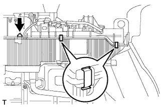
-
Insert a screwdriver at the position shown in the illustration and make a gap between the parts.
Tech Tips
Do not widen the gap excessively to avoid damaging the rear cooling unit.
-
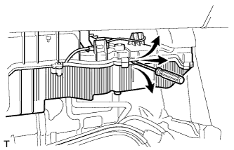
Check if cool air comes out from the gap shown in the illustration when the rear air conditioning is operated using the "Rear Cooling Unit Check" function of the intelligent tester.
OK Cool air comes out.
-
NG
GO TO AIR CONDITIONING SYSTEM Click here
OK
-
-
PERFORM ACTIVE TEST USING INTELLIGENT TESTER (HV BATTERY COOL DOWN SERVO MOTOR)
-
Connect the intelligent tester to the DLC3.
-
Turn the power switch on (IG).
-
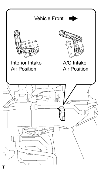
Select the following menu items: Body / Air Conditioner / Active Test / Batt Cool Down Servo Targ Pls.
-
Activate the HV battery cool down servo motor.
OK The HV battery cool down servo motor moves to the interior intake air position or A/C intake air position as commanded.
NG
GO TO AIR CONDITIONING SYSTEM Click here
OK
-
-
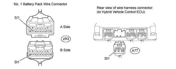
CHECK HARNESS AND CONNECTOR (NO. 1 BATTERY PACK WIRE CONNECTOR [A AND B SIDE] - HYBRID VEHICLE CONTROL ECU AND BODY GROUND)
-
Disconnect the zR3 No. 1 battery pack wire connector.
Tech Tips
For the removal and installation procedures related to the No. 1 battery pack wire connector inspection, Click here.
-
Disconnect the A77 hybrid vehicle control ECU connector.
-
Measure the resistance according to the value(s) in the table below.
Standard Resistance A Side Tester Connection Switch Condition Specified Condition zR3-17 (SI1) or A77-35 (SI1) - Body ground Power switch off 10 kΩ or higher B Side Tester Connection Switch Condition Specified Condition zR3-17 (SI1) - Body ground Power switch off 10 kΩ or higher
NG
REPAIR OR REPLACE HARNESS OR CONNECTOR
OK
-
-
INSPECT HYBRID VEHICLE CONTROL ECU (GND SHORT)
-
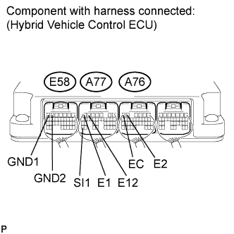
Connect connector A77 to the hybrid vehicle control ECU.
-
Measure the resistance according to the value(s) in the table below.
Standard Resistance Tester Connection Switch Condition Specified Condition A77-35 (SI1) - E58-7 (GND1) Power switch off 10 kΩ or higher A77-35 (SI1) - E58-6 (GND2) Power switch off 10 kΩ or higher A77-35 (SI1) - A77-7 (E1) Power switch off 10 kΩ or higher A77-35 (SI1) - A77-6 (E12) Power switch off 10 kΩ or higher A77-35 (SI1) - A76-6 (EC) Power switch off 10 kΩ or higher A77-35 (SI1) - A76-5 (E2) Power switch off 10 kΩ or higher E58-7 (GND1) - Body ground Power switch off Below 1 Ω
NG
REPLACE HYBRID VEHICLE CONTROL ECU Click here
OK
-
-
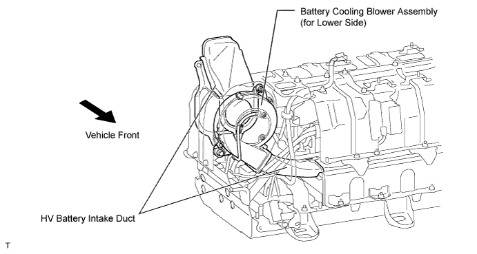
CHECK DUCT AND BLOWER
CAUTION:
Be sure to wear insulated gloves.
-
Remove the HV battery Click here.
-
Check if the HV battery intake ducts and battery cooling blower assembly (for lower side) are disconnected, damaged, or clogged with foreign objects.
Tech Tips
For the removal and installation procedures related to the HV battery intake duct and battery cooling blower assembly (for lower side), Click here.
OK The ducts and blower are not disconnected, damaged, or clogged with foreign objects.
NG
REPAIR OR REPLACE DUCT OR BLOWER Click here
OK
-
-
CHECK HARNESS AND CONNECTOR (NO. 1 BATTERY PACK WIRE CONNECTOR [B SIDE] - BATTERY COOLING BLOWER [FOR LOWER SIDE])
CAUTION:
Be sure to wear insulated gloves.
-
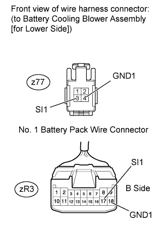
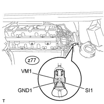
Disconnect the z77 battery cooling blower assembly (for lower side) connector.
Tech Tips
For the removal and installation procedures related to the battery cooling blower assembly (for lower side) connector inspection, Click here.
-
Measure the resistance according to the value(s) in the table below.
Standard Resistance Tester Connection Condition Specified Condition zR3-17 (SI1) - z77-3 (SI1) Always Below 1 Ω zR3-18 (GND1) - z77-4 (GND1) Always Below 1 Ω zR3-17 (SI1) - z77-4 (GND1) Always 10 kΩ or higher
NG
REPAIR OR REPLACE HARNESS OR CONNECTOR
OK
-
-
CHECK BATTERY COOLING BLOWER ASSEMBLY (for Lower Side) (VM1 VOLTAGE)
CAUTION:
Be sure to wear insulated gloves.
-
Place the HV battery in the vehicle so that measurements can be made at the battery cooling blower assembly (for lower side) connector.
Note
Make sure all the covers are installed to the HV battery when placing it in the vehicle, and then remove the covers again after the HV battery is in place.
Tech Tips
-
Follow the installation procedures to the point where the HV battery is set in the vehicle Click here.
-
Do not install the service plug grip.
-
-
Reconnect all the connectors that were disconnected when the HV battery was removed.
-
Connect the intelligent tester to the DLC3.
-
Turn the power switch on (IG).
-
Select the following menu items: Powertrain / Hybrid Control / Data List / VMF Fan Motor Voltage 2.
-
Using a service wire, connect terminals z77-3 (SI1) and z77-4 (GND1) of the battery cooling blower assembly (for lower side) connector.
CAUTION:
Do not touch the fan while it is operating.
-
While the battery cooling blower assembly (for lower side) is operating, compare the value in the data list ("VMF Fan Motor Voltage 2") with the voltage value that was actually measured at the battery cooling blower assembly (for lower side) connector.
OK Tester Connection Switch Condition Specified Condition z77-2 (VM1) - z77-4 (GND1) Power switch on (IG) Difference between the value in the data list ("VMF Fan Motor Voltage 2") and the actual measurement value is 1 V or less. Tech Tips
-
When the battery smart unit is functioning normally, it will control the voltage to within 1 V of the actual measurement value.
-
Perform this inspection with the battery cooling blower assembly (for lower side) connector connected.
-
If the power switch is turned on (IG) with the service plug grip removed, DTC P0A0D-350 for the interlock switch system will be set. If this DTC is output, clear the DTC using the intelligent tester Click here.
-
NG
REPLACE BATTERY SMART UNIT Click here
OK 
REPLACE BATTERY COOLING BLOWER ASSEMBLY (for Lower Side) Click here
-