FRAME WIRE (for LHD) INSTALLATION

-
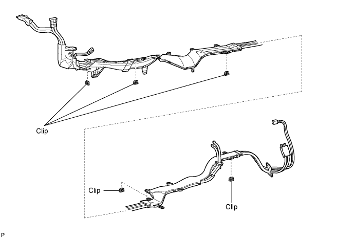
INSTALL FRAME WIRE
-
Install the frame wire to the vehicle with 5 new clips.
-
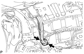
Pass the frame wire to the cabin and install the 2 bolts.
- Torque:
- 5.5 N*m { 56 kgf*cm, 49 in.*lbf }
-
Pass the frame wire into the cabin and secure the grommet.
-
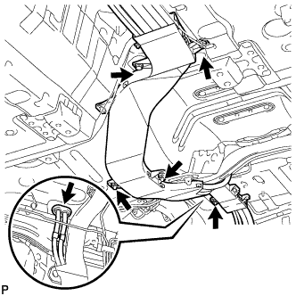
Install the 3 nuts and 2 bolts.
- Torque:
- 5.5 N*m { 56 kgf*cm, 49 in.*lbf }
-
Install the 4 nuts and bolt.
- Torque:
- 5.5 N*m { 56 kgf*cm, 49 in.*lbf }
-
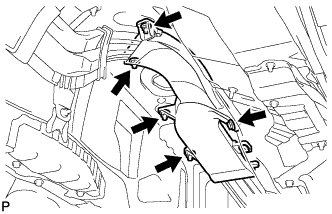
Install the 3 nuts and bolt.
- Torque:
- 5.5 N*m { 56 kgf*cm, 49 in.*lbf }
-
Install the 2 bolts and clamp.
- Torque:
- 5.5 N*m { 56 kgf*cm, 49 in.*lbf }
-
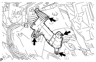
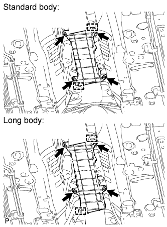
Engage the 2 claws, and connect the frame wire to the engine room No. 1 junction block.
-
Secure the frame wire to the engine room No. 1 junction block with the 2 nuts.
- Torque:
- 13 N*m { 127 kgf*cm, 9 ft.*lbf }
-
-
INSTALL WIRE HARNESS PROTECTOR
-
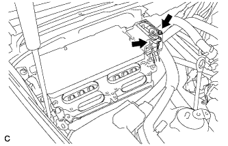
Install the 3 nuts, new clip and wire harness protector.
- Torque:
- 5.5 N*m { 56 kgf*cm, 49 in.*lbf }
-
Install the 4 nuts, 2 clamps and wire harness protector.
- Torque:
- 5.5 N*m { 56 kgf*cm, 49 in.*lbf }
-
-
CONNECT FRAME WIRE
-
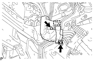
Using an insulated tool, connect the frame wire to the inverter with converter assembly with the bolt.
CAUTION:
Wear insulated gloves.
- Torque:
- 8.0 N*m { 82 kgf*cm, 71 in.*lbf }
-
Using an insulated tool, install the connector cover with the 2 bolts.
CAUTION:
Wear insulated gloves.
- Torque:
- 8.0 N*m { 82 kgf*cm, 71 in.*lbf }
-
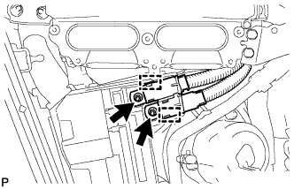
Attach the claw and connect the frame wire to the luggage terminal.
CAUTION:
Wear insulated gloves.
-
Using an insulated tool, connect the frame wire with the 2 nuts.
- Torque:
- 13 N*m { 127 kgf*cm, 9 ft.*lbf }
-
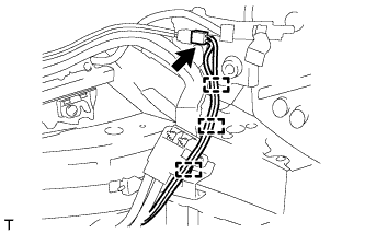
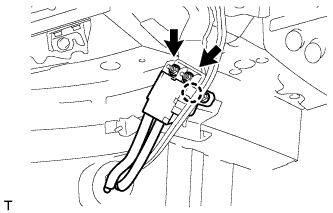
Connect the connector and attach the 3 clamps.
-
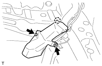
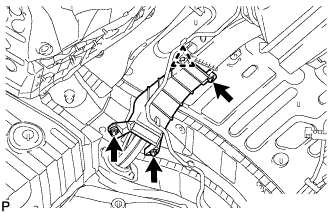
Install the No. 15 wiring harness protector with the 2 nuts and attach the claw.
- Torque:
- 8.0 N*m { 82 kgf*cm, 71 in.*lbf }
-
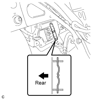
Install the battery shield contact as shown in the illustration.
Note
Be sure to install the battery shield contact in the correct direction.
-
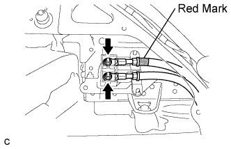
Using an insulated tool, connect the frame wire to the HV battery with the 2 nuts.
- Torque:
- 9.0 N*m { 92 kgf*cm, 80 in.*lbf }
Note
Be sure to align the red mark on the HV battery with the red part of the terminal block.
-
-
INSTALL TOOL BOX (w/o Spare Tire)
-
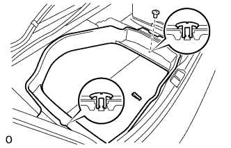
Install the tool box with the 2 clips.
-
-
INSTALL SPARE WHEEL GUARD SUB-ASSEMBLY (w/o Spare Tire)
-
INSTALL SPARE WHEEL GUARD SUB-ASSEMBLY (w/ Spare Tire)
-
Install the spare wheel guard sub-assembly with the 2 clips.
-
-
INSTALL NO. 2 HYBRID BATTERY SHIELD SUB-ASSEMBLY

Text in Illustration *a Battery Cover Lock Striker *b Push CAUTION:
Be sure to wear insulated gloves.
-
Install the No. 2 hybrid battery shield sub-assembly to the HV battery.
-
Install the No. 2 hybrid battery shield sub-assembly with the 2 nuts in the order shown in the illustration.
- Torque:
- 8.0 N*m { 82 kgf*cm, 71 in.*lbf }
-
Install the battery cover lock striker and push the button.
-
-
INSTALL NO. 1 CENTER FLOOR TO BRACE EXTENSION
-
Install the No. 1 center floor to brace extension with the 3 clips.
-
-
INSTALL LUGGAGE COMPARTMENT TRIM COVER ASSEMBLY RH
-
INSTALL REAR SUSPENSION MEMBER SUB-ASSEMBLY
-
INSTALL FUEL TANK ASSEMBLY
-
INSTALL REAR SEAT ASSEMBLY
-
for Fixed Seat Type: Click here
-
for Ottoman: Click here
-
for Power Seat: Click here
-
-
INSTALL ENGINE ASSEMBLY WITH TRANSMISSION
-
INSTALL SERVICE PLUG GRIP
-
CONNECT CABLE TO AUXILIARY BATTERY NEGATIVE TERMINAL
Note
When disconnecting the cable, some systems need to be initialized after the cable is reconnected Click here.
-
INSTALL BATTERY SERVICE HOLE COVER LH
-

Text in Illustration *A for Standard *B for Ottoman Attach the battery service hole cover LH with the clip and fastening tape.
-
-
INSTALL DECK TRIM SIDE BOARD LH (w/o Spare Tire)
-

Attach the 2 clips to install the deck trim side board LH.
-
-
INSTALL DECK BOARD ASSEMBLY (w/o Spare Tire)
-
INSTALL LUGGAGE COMPARTMENT MAT SUB-ASSEMBLY (w/ Spare Tire)
