FRAME WIRE (for LHD) REMOVAL

-
PRECAUTION
CAUTION:
Be sure to read Precaution thoroughly before servicing Click here.
Note
After turning the power switch off, waiting time may be required before disconnecting the cable from the auxiliary battery terminal. Therefore, make sure to read the disconnecting the cable from the auxiliary battery terminal notice before proceeding with work Click here.
-
REMOVE LUGGAGE COMPARTMENT MAT SUB-ASSEMBLY (w/ Spare Tire)

-
REMOVE DECK BOARD ASSEMBLY (w/o Spare Tire)

-
REMOVE DECK TRIM SIDE BOARD LH (w/o Spare Tire)
-

Detach the 2 clips and remove the deck trim side board LH.
-
-
REMOVE BATTERY SERVICE HOLE COVER LH
-

Text in Illustration *A for Standard *B for Ottoman *1 Fastening Tape Detach the clip, fastening tape and remove the battery service hole cover LH.
-
-
DISCONNECT CABLE FROM AUXILIARY BATTERY NEGATIVE TERMINAL
Note
When disconnecting the cable, some systems need to be initialized after the cable is reconnected Click here.
-
REMOVE SERVICE PLUG GRIP
-
REMOVE ENGINE ASSEMBLY WITH TRANSMISSION
-
REMOVE REAR SEAT ASSEMBLY
-
for Power Seat: Click here
-
for Ottoman: Click here
-
for Fixed Seat Type: Click here
-
-
REMOVE FUEL TANK ASSEMBLY
-
REMOVE REAR SUSPENSION MEMBER SUB-ASSEMBLY
-
REMOVE LUGGAGE COMPARTMENT TRIM COVER ASSEMBLY RH
-
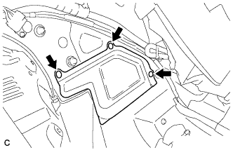
REMOVE NO. 1 CENTER FLOOR TO BRACE EXTENSION
-
Remove the 3 clips and No. 1 center floor to brace extension.
-
-
REMOVE NO. 2 HYBRID BATTERY SHIELD SUB-ASSEMBLY
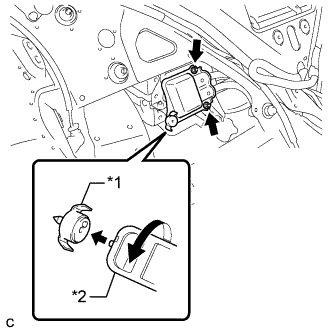
Text in Illustration *1 Battery Cover Lock Striker *2 Service Plug Grip CAUTION:
Be sure to wear insulated gloves.
-
Using the service plug grip, release the battery cover lock striker.
-
Remove the 2 nuts and disconnect the No. 2 HV battery shield sub-assembly from the HV battery.
-
-
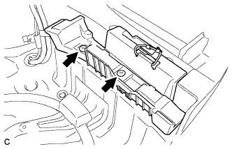
REMOVE SPARE WHEEL GUARD SUB-ASSEMBLY (w/ Spare Tire)
-
Remove the 2 clips and spare wheel guard sub-assembly.
-
-
REMOVE SPARE WHEEL GUARD SUB-ASSEMBLY (w/o Spare Tire)
-
REMOVE TOOL BOX (w/o Spare Tire)
-
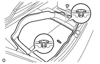
Remove the 2 clips and tool box.
-
-
DISCONNECT FRAME WIRE
CAUTION:
Wear insulated gloves.
-
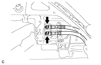
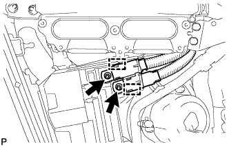
Using an insulated tool, remove the 2 nuts, and disconnect the frame wire from the HV battery.
Note
Insulate the terminals of the removed high voltage wire with insulating tape.
-
Remove the battery shield contact from the HV battery.
-
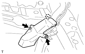
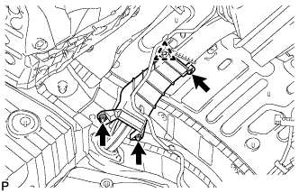
Remove the 2 nuts, detach the claw and remove the No. 15 wiring harness protector.
-
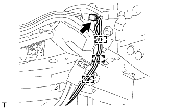
Disconnect the connector and detach the 3 clamps.
-
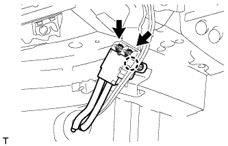
Detach the claw.
-
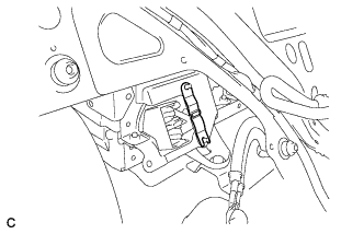
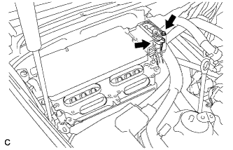
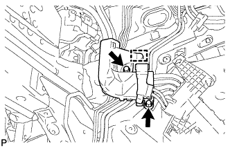
Using an insulated tool, remove the 2 nuts and separate the frame wire from the luggage terminal.
-
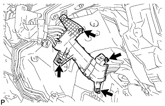
Using an insulated tool, remove the 2 bolts and connector cover assembly.
CAUTION:
Wear insulating gloves.
-
Using an insulated tool, remove the bolt and disconnect the frame wire from the inverter with converter assembly.
Note
Cover the hole where the cable was connected with tape or equivalent (non-residue type) to prevent entry of foreign matter.
-
-
REMOVE WIRE HARNESS PROTECTOR
-
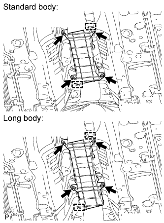
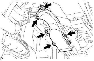
Remove the 4 nuts, 2 clamps and wire harness protector.
-
Remove the 3 nuts, clip and wire harness protector.
Tech Tips
When removing the clip, break the claw on the clip. This clip cannot be reused.
-
-
REMOVE FRAME WIRE
-
Remove the 2 nuts from the frame wire.
-
Release the 2 claws and disconnect the frame wire from the engine room No. 1 junction block.
-
Remove the 2 bolts and clamp.
-
Remove the 3 nuts and bolt.
-
Remove the 4 nuts and bolt.
-
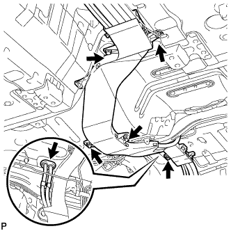
Remove the 3 nuts and 2 bolts.
-
Remove the grommet and pull out the frame wire from the cabin.
-
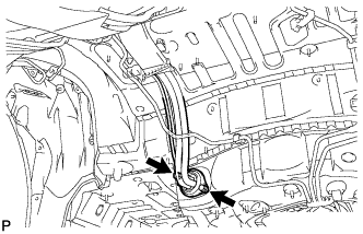
Remove the 2 bolts and pull out the frame wire from the cabin.
-
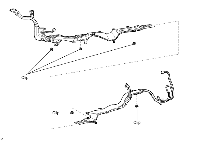
Remove the 5 clips and frame wire from the vehicle.
Tech Tips
When removing the clips, break the claws on the clips. These clips cannot be reused.
-