INVERTER WITH CONVERTER (for LHD) INSTALLATION

-
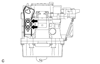
INSTALL HIGH VOLTAGE FUSE
-
Install the high voltage fuse with 2 new nuts.
- Torque:
- 4.0 N*m { 41 kgf*cm, 35 in.*lbf }
Note
Be sure to use a torque wrench to tighten the nuts.
Tech Tips
Perform this procedure only when replacement of the high voltage fuse is necessary.
-
-
INSTALL INVERTER COOLING PIPE BRACKET
-
Install the inverter cooling pipe bracket to the inverter with converter assembly with the bolt.
- Torque:
- 8.0 N*m { 82 kgf*cm, 71 in.*lbf }
-
-
INSTALL NO. 6 INVERTER BRACKET
-
Install the No. 6 inverter bracket to the inverter with converter assembly with the bolt.
- Torque:
- 8.0 N*m { 82 kgf*cm, 71 in.*lbf }
-
-
INSTALL NO. 3 INVERTER BRACKET
-
Install the No. 3 inverter bracket to the inverter with converter assembly with the 2 bolts.
- Torque:
- 8.0 N*m { 82 kgf*cm, 71 in.*lbf }
-
-
INSTALL NO. 2 INVERTER BRACKET
-
Install the No. 2 inverter bracket to the inverter with converter assembly with the 2 bolts.
- Torque:
- 8.0 N*m { 82 kgf*cm, 71 in.*lbf }
-
-
INSTALL NO. 1 INVERTER COOLING HOSE ASSEMBLY
-
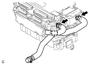
Install the No. 1 inverter cooling hose assembly and No. 1 inverter cooling inlet hose to the inverter with converter assembly with the 2 clips and clamp.
Note
-
Do not deform, bend or scratch the pipes of the inverter with converter assembly. The pipes are made of aluminum and must remain undamaged to maintain proper seal with the rubber hoses.
-
The inverter hose is connected to the cooling system built into the inverter. Do not apply excessive force to the inverter hose, or the inverter cooling system may be damaged.
-
-
Connect the hose clamp.
-
-
INSTALL INVERTER WITH CONVERTER ASSEMBLY
CAUTION:
Wear insulating gloves.
-
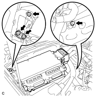
Install the inverter with converter assembly with the bolt, 3 nuts and inverter bracket.
- Torque:
- 23 N*m { 235 kgf*cm, 17 ft.*lbf }
Note
-
Since the inverter with converter assembly is very heavy, 2 people are needed to install the inverter with converter assembly. When installing the inverter with converter assembly, do not damage the parts around it.
-
To prevent damage, do not hold the inverter with converter assembly by the connectors.
-
To prevent damage due to static electricity, do not touch the terminals of the disconnected connectors.
-
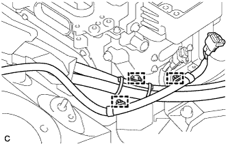
Connect the 3 wire harness clamps.
-
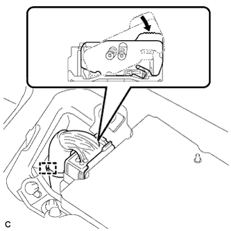
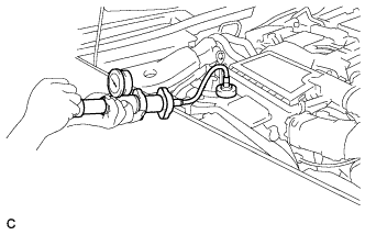
Connect the low voltage connector of the inverter with converter assembly and lock the connector with the lock lever.
-
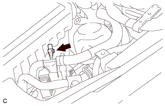
Connect the wire harness clamp.
-
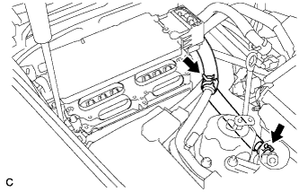
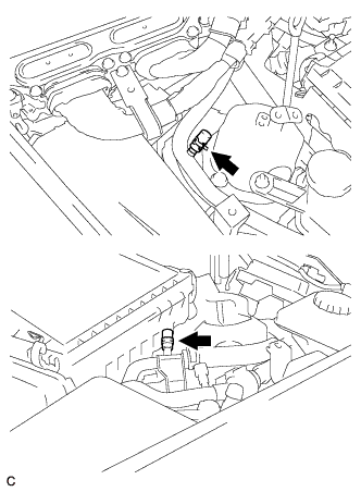
Connect the 2 inverter hoses with the 2 clips.
-
-
CONNECT AIR CONDITIONING HARNESS
CAUTION:
Wear insulating gloves.
-
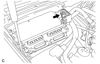
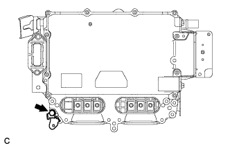
Connect the air conditioning harness to the inverter with converter assembly.
-
-
CONNECT FRAME WIRE
CAUTION:
Wear insulating gloves.
-
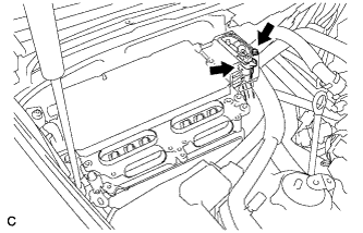
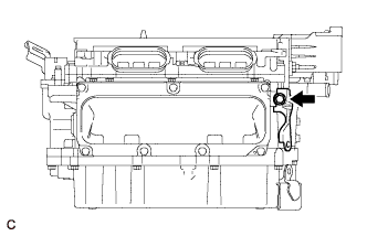
Using an insulated tool, connect the frame wire to the inverter with converter assembly with the bolt.
- Torque:
- 8.0 N*m { 82 kgf*cm, 71 in.*lbf }
-
-
CONNECT GENERATOR CABLE
CAUTION:
Wear insulating gloves.
-
Using an insulated tool, connect the generator cable to the inverter with converter assembly.
-
Secure the generator cable to the inverter with converter assembly with the 5 bolts.
- Torque:
- 8.0 N*m { 82 kgf*cm, 71 in.*lbf }
Note
-
When installing the bolts that secure the cable, do not damage anything inside the inverter with converter assembly.
-
Make sure that no foreign matter is present on the terminal block.
-
Be sure to tighten the bolt to the specified torque. Failure to do so may damage the bolt.
-
-
CONNECT MOTOR CABLE
CAUTION:
Wear insulating gloves.
-
Using an insulated tool, connect the motor cable to the inverter with converter assembly.
-
Secure the motor cable to the inverter with converter assembly with the 5 bolts.
- Torque:
- 8.0 N*m { 82 kgf*cm, 71 in.*lbf }
Note
-
When installing the bolts that secure the cable, do not damage anything inside the inverter with converter assembly.
-
Make sure that no foreign matter is present on the terminal block.
-
Be sure to tighten the bolt to the specified torque. Failure to do so may damage the bolt
-
Install the motor cable bracket with the 3 bolts.
- Torque:
- 8.0 N*m { 82 kgf*cm, 71 in.*lbf }
-
-
INSTALL INVERTER TERMINAL COVER
CAUTION:
Wear insulating gloves.
-
Set the inverter terminal cover to the inverter with converter assembly.
Note
-
Check that the sealing rubber is securely installed to the inverter terminal cover before installing the cover.
-
Making sure that there are no foreign objects on the waterproofed parts before installing the inverter terminal cover.
-
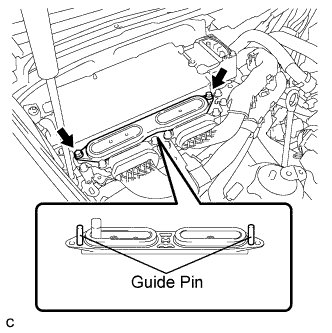
Install the inverter terminal cover while inserting the guide pins on both sides of the cover into guide pin holes of the inverter case.
-
When removing the inverter terminal cover, do not bend the connector terminals around the interlock part.
-
-
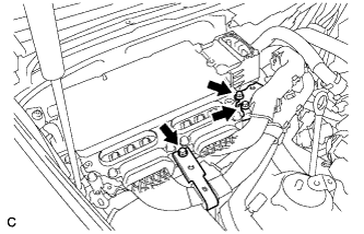
Push in both ends of the inverter terminal cover horizontally by hand.
Note
-
Insert the inverter terminal cover horizontally to prevent it from tilting. Failure to do so may damage the inverter terminal cover guide pins.
-
Make sure that both the inverter terminal cover bolt holes are aligned and in contact with the holes in the inverter case.
-
-
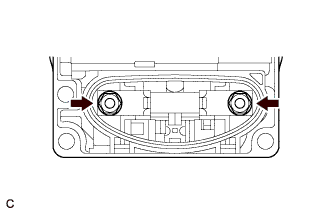
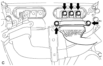
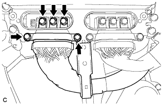
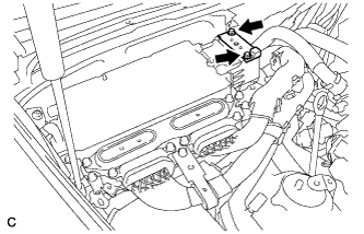
Using an insulated tool, secure the inverter terminal cover to the inverter with converter assembly with the 2 bolts.
- Torque:
- 8.0 N*m { 82 kgf*cm, 71 in.*lbf }
-
-
INSTALL CONNECTOR COVER ASSEMBLY
CAUTION:
Wear insulating gloves.
-
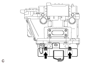
Using an insulated tool, install the connector cover assembly with the 2 bolts.
- Torque:
- 8.0 N*m { 82 kgf*cm, 71 in.*lbf }
-
-
INSTALL SERVICE PLUG GRIP
-
CONNECT CABLE TO AUXILIARY BATTERY NEGATIVE TERMINAL
Note
When disconnecting the cable, some systems need to be initialized after the cable is reconnected Click here.
-
INSTALL BATTERY SERVICE HOLE COVER LH
-

Text in Illustration *A for Standard *B for Ottoman Attach the battery service hole cover LH with the clip and fastening tape.
-
-
INSTALL DECK TRIM SIDE BOARD LH (w/o Spare Tire)
-

Attach the 2 clips to install the deck trim side board LH.
-
-
INSTALL DECK BOARD ASSEMBLY (w/o Spare Tire)

-
INSTALL LUGGAGE COMPARTMENT MAT SUB-ASSEMBLY (w/ Spare Tire)

-
ADD COOLANT (for Inverter)
Note
-
Do not reuse the drained coolant because it may contain foreign objects.
-
If the vehicle is driven with air in the inverter cooling system, the following DTCs may be set.
DTC Code Detection Item P0A01-725 Motor Electronics Coolant Temperature Sensor Circuit Range / Performance P0A01-726 Motor Electronics Coolant Temperature Sensor Circuit Range / Performance P0A78-284 Drive Motor "A" Inverter Performance P0A7A-322 Generator Inverter Performance P0A93-346 Inverter Cooling System Performance P0A94-553 DC / DC Converter Performance P0AEE-276 Motor Inverter Temperature Sensor "A" Circuit Range / Performance P0AEE-277 Motor Inverter Temperature Sensor "A" Circuit Range / Performance P3221-314 Generator Inverter Temperature Sensor Circuit Range / Performance P3221-315 Generator Inverter Temperature Sensor Circuit Range / Performance P3226-562 DC/DC Boost Converter Temperature Sensor P3226-563 DC/DC Boost Converter Temperature Sensor
Tech Tips
-
for LHD:
Coolant (for inverter) capacity: 2.6 liters (2.7 US qts, 2.3 Imp. qts.)
-
for RHD:
Coolant (for inverter) capacity: 2.5 liters (2.5 US qts, 2.2 Imp. qts.)
-
for LHD:
Remove the 2 clips and 2 plugs from the tubes.
Note
Do not reuse the clips or plugs.
-
for RHD:
Remove the clip and plug from the tube.
Note
Do not reuse the clip or plug.
-
Add coolant to the reserve tank.
-
for LHD:
Install 2 new plugs and 2 new clips to the tubes.
-
for RHD:
Install a new plug and new clip to the tube.
-
Connect the intelligent tester to the DLC3.
-
Select the following menu items: Powertrain / Hybrid Control / Active Test / Activate the Water Pump.
Tech Tips
The water pump can also be operated using inspection mode Click here.
-
While adding coolant so that the coolant level is kept around the FULL line of the inverter reserve tank, operate the water pump for 3 minutes or more and then stop it for 1 minute or more.
-
While adding coolant so that the coolant level is kept around the FULL line of the inverter reserve tank, operate the water pump for 1 minute or more and stop it for 1 minute or more. Repeat this procedure until bleeding is completed.
Standard When the operation sound of the water pump becomes small or when no air bubbles can be seen in the inverter reserve tank, bleeding of the coolant system is complete. Tech Tips
-
If the water pump operates without a sufficient amount of coolant for approximately 5 seconds, the protective circuit will activate to stop the water pump for approximately 15 seconds. If a sufficient amount of coolant is added, the water pump will start operating automatically.
-
If an excessive amount of coolant is added to the inverter reserve tank, coolant may overflow when operation of the water pump is stopped.
-
-
After bleeding is completed, add coolant to the FULL level, and install the inverter reserve tank cap.
Note
Make sure to add more coolant than was drained initially.
-
-
INSPECT FOR COOLANT LEAK (for Inverter)
-
Remove the reserve tank cap.
CAUTION:
To avoid the danger of being burned, do not remove the reserve tank cap while the coolant for the inverter is still hot.
-
Install the radiator cap tester.
-
Pump the radiator cap tester to 37 kPa (0.38 kgf/ cm2, 5.4 psi), and then check that the pressure does not drop.
Tech Tips
If the pressure drops, check the hoses, radiator, water pump, inverter with converter, and hybrid vehicle transaxle assembly for leakage.
-
Reinstall the reserve tank cap.
-
-
INSTALL FRONT CENTER FLOOR COVER
-
Install the front center floor cover with the 3 screws, 2 bolts and clip.
- Torque:
- 5.4 N*m { 55 kgf*cm, 48 in.*lbf }
-
-
INSTALL INVERTER COVER ASSEMBLY RH
-
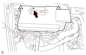
Align the locating hole of the inverter cover assembly RH with the locating pin of the inverter with converter assembly. Set the inverter cover assembly RH to the inverter with converter assembly.
-
Press the positions where the clips are to secure the inverter cover assembly RH to the inverter with converter assembly.
-
-
INSTALL MOTOR CABLE COVER RH
-
Install the motor cable cover RH with the 2 clips.
-
-
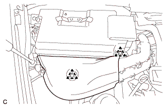
INSTALL COWL TOP VENTILATOR LOUVER RH
-
Install the hood to cowl top seal with the 4 clips.
-
Install the cowl top ventilator louver RH with the 6 clips.
-
-
INSTALL FRONT UPPER FENDER PROTECTOR RH
Tech Tips
Use the same procedures described for the LH side Click here.
-
INSTALL ENGINE ROOM SIDE COVER RH
-
Install the engine room side cover RH with the 5 clips.
-
-
INSTALL ENGINE ROOM SIDE COVER LH
-
Install the engine room side cover LH with the 5 clips.
-
-
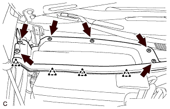
INSTALL V-BANK COVER SUB-ASSEMBLY
-

After sliding the V-bank cover sub-assembly from the vehicle front to the rear to attach the 2 clips labeled A, attach the 4 clips labeled B and install the V-bank cover sub-assembly.
CAUTION:
-
Make sure the clips are attached securely.
-
Attaching the clips forcefully or hitting the top of the clips may damage them.
-
-