HYBRID CONTROL SYSTEM Transmission Control Switch Circuit
DESCRIPTION
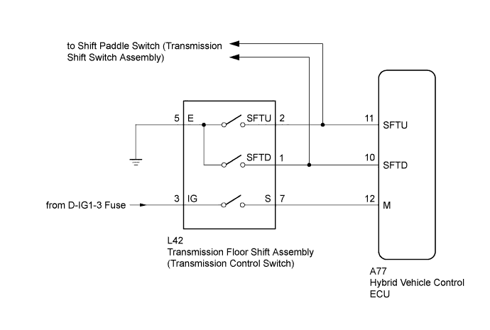
When the shift lever is in S, the shift range position can be changed freely using the sequential gate of the transmission floor shift assembly.
WIRING DIAGRAM
INSPECTION PROCEDURE
PROCEDURE
-
READ VALUE USING INTELLIGENT TESTER (SPORTS MODE)
-
Connect the intelligent tester to the DLC3.
-
Turn the power switch on (IG).
-
Enter the following menus: Powertrain / Hybrid Control / Data List / Sports Mode.
-
Read the data list.
OK Tester Display Description Inspection Condition Specified Condition Sports Mode Indicates the S position Shift from D to S and back to D Changes from OFF to ON and back to OFF
NG 
CHECK HARNESS AND CONNECTOR (POWER SOURCE CIRCUIT) Click here
OK 
-
-
READ VALUE USING INTELLIGENT TESTER (SPORT UP SIG, SPORT DOWN SIG)
-
Enter the following menus: Powertrain / Hybrid Control / Data List / Sports Shift UP Signal, Sports Shift Down Signal.
-
Read the data list.
OK Tester Display Description Inspection Condition Specified Condition Sports Shift UP Signal Indicates the transmission control switch (+) Shift from S to + and back to S Changes from OFF to ON and back to OFF Sports Shift Down Signal Indicates the transmission control switch (-) Shift from S to - and back to S Changes from OFF to ON and back to OFF
NG
INSPECT TRANSMISSION FLOOR SHIFT ASSEMBLY (TRANSMISSION CONTROL SWITCH) Click here
OK
-
-
CHECK FOR INTERMITTENT PROBLEMS
-
Check for intermittent problems Click here.
-
Move the shift lever to the S position and jiggle the wire harness and connector.
-
Move the shift lever to the + and - positions and jiggle the wire harness and connector.
-
NG 
REPAIR OR REPLACE MALFUNCTIONING PARTS, COMPONENT AND AREA
OK 
REPLACE HYBRID VEHICLE CONTROL ECU Click here
-
-
INSPECT TRANSMISSION FLOOR SHIFT ASSEMBLY (TRANSMISSION CONTROL SWITCH)
-
Disconnect the transmission control switch connector.
-
Measure the resistance according to the value(s) in the table below.
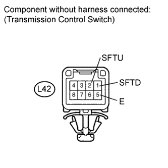
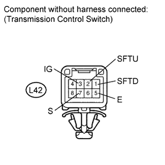
Standard resistance Tester Connection Sequential Gate Specified Condition L42-2 (SFTU) - L42-5 (E) + position Below 1 Ω L42-2 (SFTU) - L42-5 (E) Neutral
(S position)
10 kΩ or higher L42-1 (SFTD) - L42-5 (E) L42-1 (SFTD) - L42-5 (E) - position Below 1 Ω
NG
REPLACE TRANSMISSION FLOOR SHIFT ASSEMBLY Click here
OK
-
-
CHECK HARNESS AND CONNECTOR (TRANSMISSION CONTROL SWITCH - HYBRID VEHICLE CONTROL ECU)
-
Connect the transmission control switch connector.
-
Disconnect connector A77 from the hybrid vehicle control ECU.
-
Disconnect the spiral cable sub-assembly connector.
-
Measure the resistance according to the value(s) in the table below.
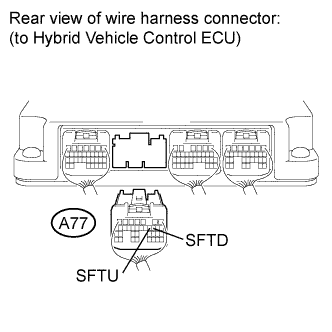
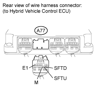
Standard resistance Tester Connection Sequential Gate Specified Condition A77-11 (SFTU) - Body ground + position Below 1 Ω A77-11 (SFTU) - Body ground Neutral
(S position)
10 kΩ or higher A77-10 (SFTD) - Body ground A77-10 (SFTD) - Body ground - position Below 1 Ω
NG
REPAIR OR REPLACE HARNESS OR CONNECTOR
OK
REPLACE HYBRID VEHICLE CONTROL ECU Click here
-
-
CHECK HARNESS AND CONNECTOR (POWER SOURCE CIRCUIT)
-
Disconnect the transmission control switch connector.
-
Turn the power switch on (IG).
-
Measure the voltage according to the value(s) in the table below.
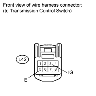
Standard voltage Tester Connection Switch Condition Specified Condition L42-3 (IG) - L42-5 (E) Power switch on (IG) 11 to 14 V -
Turn the power switch off.
-
Measure the resistance according to the value(s) in the table below.
Standard resistance Tester Connection Condition Specified Condition L42-5 (E) - Body ground Always Below 1 Ω
NG
REPAIR OR REPLACE HARNESS OR CONNECTOR
OK
-
-
INSPECT TRANSMISSION FLOOR SHIFT ASSEMBLY (TRANSMISSION CONTROL SWITCH)
-
Measure the resistance according to the value(s) in the table below.
Standard resistance Tester Connection Sequential Gate Specified Condition L42-3 (IG) - L42-7 (S) Except for S position 10 kΩ or higher L42-3 (IG) - L42-7 (S) S position Below 1 Ω L42-2 (SFTU) - L42-5 (E) + position Below 1 Ω L42-2 (SFTU) - L42-5 (E) Neutral
(S position)
10 kΩ or higher L42-1 (SFTD) - L42-5 (E) L42-1 (SFTD) - L42-5 (E) - position Below 1 Ω
NG
REPLACE TRANSMISSION FLOOR SHIFT ASSEMBLY Click here
OK
-
-
CHECK HARNESS AND CONNECTOR (TRANSMISSION CONTROL SWITCH - HYBRID VEHICLE CONTROL ECU)
-
Connect the transmission control switch connector.
-
Disconnect connector A77 from the hybrid vehicle control ECU.
-
Turn the power switch on (IG).
-
Measure the voltage according to the value(s) in the table below.
Standard voltage Tester Connection Condition Specified Condition A77-12 (M) - A77-7 (E1) Power switch on (IG)
Except for S position
Below 1 V A77-12 (M) - A77-7 (E1) Power switch on (IG)
S position
11 to 14 V Note
Turning the power switch on (IG) with the hybrid vehicle control ECU connector disconnected causes other DTCs to be stored. Clear the DTCs after performing this inspection.
-
Turn the power switch off.
-
Disconnect the spiral cable sub-assembly connector.
-
Measure the resistance according to the value(s) in the table below.
Standard resistance Tester Connection Condition Specified Condition A77-11 (SFTU) - Body ground + position Below 1 Ω A77-11 (SFTU) - Body ground Neutral
(S position)
10 kΩ or higher A77-10 (SFTD) - Body ground A77-10 (SFTD) - Body ground - position Below 1 Ω
NG
REPAIR OR REPLACE HARNESS OR CONNECTOR
OK
REPLACE HYBRID VEHICLE CONTROL ECU Click here
-