HYBRID CONTROL SYSTEM EV Drive Mode Switch Circuit
DESCRIPTION
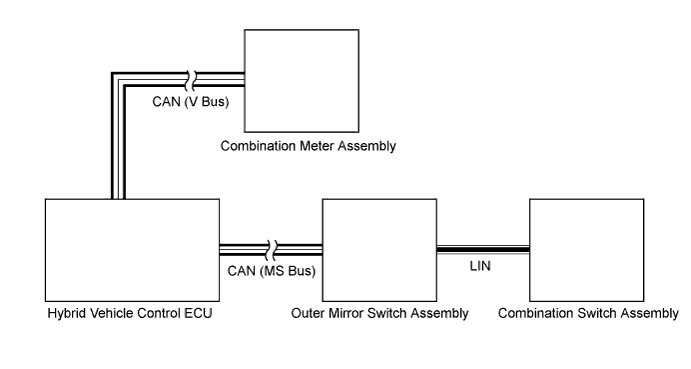
The EV mode switch is built into the combination switch assembly. EV mode switch signals are sent to the outer mirror switch assembly via LIN communication. The signals are then sent to the hybrid vehicle control ECU via CAN communication. If EV mode switch signals are input to the hybrid vehicle control ECU, the ECU sends signals to the combination meter assembly via CAN communication to turn on the EV mode light.
If any of the following conditions are not met, EV mode may not be turned on or the mode may be cancelled. (A buzzer sounds to indicate that the transition to EV mode is cancelled and a message is displayed on multi-information display.)
| EV Mode Entry Condition | Data List Item | Specified Condition |
|---|---|---|
| HV battery charge level | State of Charge | Approximately 50% or more |
| Accelerator pedal position | Accelerator Degree | Approximately 30% or less |
| Engine coolant temperature | Engine Coolant Temp | 50°C (122°F) or more |
| HV battery temperature | Temp of Batt TB 1 to 4 | 10 to 40°C (50 to 104°F) |
| Vehicle speed | - |
|
| Defroster | - | OFF |
| Cruise control | - | OFF |
| Win (Watts in) | Charge Control Value | -20000 W or less |
| Wout (Watts out) | Discharge Control Value | 20000 W or more |
| Shift lever position | - | N position (The engine is not running.) |
| ATF temperature | T/M Oil Temperature | 10 to 80°C (50 to 176°F) |
INSPECTION PROCEDURE
PROCEDURE
-
ASK VEHICLE CONDITION
-
Ask the customer if a buzzer sounded to indicate that the transition to EV mode was cancelled and a message was displayed on multi-information display when he or she pressed the EV mode switch.
Result Result Proceed to No buzzer sounded and no message was displayed on multi-information display. A A buzzer sounded and a message was displayed on multi-information display. B Tech Tips
If a buzzer sounds and a message is displayed on multi-information display, one or more of the EV mode entry conditions have not been met. Check that all of the EV mode entry conditions have been met before pressing the EV mode switch.
B 
COMPLETED
A 
-
-
READ VALUE USING GTS (CAN BUS CHECK)
Tech Tips
ECUs that are correctly connected to the CAN communication system can be displayed on the GTS.
-
Connect the GTS to the DLC3.
-
Turn the power switch on (IG).
-
Enter the following menus: System Select / CAN Bus Check.
Result Result Proceed to All of the ECUs and sensors that are currently connected to the CAN communication system are displayed. A None of the ECUs and sensors that are currently connected to the CAN communication system are displayed, or some of them are not displayed. B
(for LHD)
C
(for RHD)
B
GO TO CAN COMMUNICATION SYSTEM Click here
C
GO TO CAN COMMUNICATION SYSTEM Click here
A
-
-
PERFORM ACTIVE TEST USING GTS (COMBINATION METER)
-
Enter the following menus: Body Electrical / Combination Meter / Active Test / EV Mode Indicator.
-
Perform the "EV Mode Indicator" active test.
Tester Display Test Part Control Range Diagnostic Note EV Mode Indicator EV mode indicator light ON or OFF - Result Result Proceed to The EV mode indicator light comes on. A The EV mode indicator light does not come on. B
B
GO TO METER / GAUGE SYSTEM Click here
A
-
-
READ VALUE USING GTS (CENTER CONSOLE SWITCH)
-
Enter the following menus: Body Electrical / Center Console Switch / Data List / EV Mode Switch.
-
Read the data list.
Tester Display Measurement Item / Range Normal Condition Diagnostic Note EV Mode Switch EV mode switch status / ON or OFF When turning power switch on (IG): OFF
↓
EV mode switch pressed: ON
↓
EV mode switch not pressed : OFF
- Result Result Proceed to The tester display changes according to the EV mode switch operation. A The tester display does not change according to the EV mode switch operation. B
B
REPLACE COMBINATION SWITCH ASSEMBLY Click here
A 
CHECK FOR INTERMITTENT PROBLEMS Click here
-