HYBRID CONTROL SYSTEM, Diagnostic DTC:P3246-202

| DTC Code | DTC Name |
|---|---|
| P3246-202 | Short in Drive Motor "A" Inverter Circuit |
DESCRIPTION
For a description of the inverter, Click here.
| DTC No. | INF Code | DTC Detection Condition | Trouble Area |
|---|---|---|---|
| P3246 | 202 | Malfunction (short circuit) in the motor inverter inside the inverter with converter assembly |
|
INSPECTION PROCEDURE
Note
-
DTC P3246-202 is stored after any of DTCs P0A78-113, 128, 284, 286, 287, 505, 506, 806, 807 and 808 are stored. After troubleshooting and repairing DTC P3246-202, be sure to troubleshoot all the other DTCs.
-
The monitor cable and hybrid vehicle transmission assembly may be affected depending on the vehicle operating conditions if a short occurs in the inverter with converter assembly. If DTC P3246-202 is output, inspect the motor cable and hybrid vehicle transmission assembly and replace the defective parts.
-
After completing the repair, test-drive the vehicle at a speed of approximately 40 km/h (25 mph) for 1 minute and check that DTC P0A90-251 (Driver Motor "A" Performance) is not output. If DTC P0A90-251 (Driver Motor "A" Performance) is output, replace the hybrid vehicle transmission assembly.
PROCEDURE
-
CHECK HYBRID VEHICLE TRANSMISSION ASSEMBLY (MG2)
CAUTION:
Be sure to wear insulated gloves.
-
Remove the service plug grip Click here.
Note
After removing the service plug grip, do not turn the power switch on (READY) unless instructed by the repair manual because this may cause a malfunction.
-
Check that the service plug grip is not installed.
-
Disconnect the generator cable and motor cable from the inverter with converter assembly.
Tech Tips
For the removal and installation procedures related to the generator cable and motor cable, Click here.
-
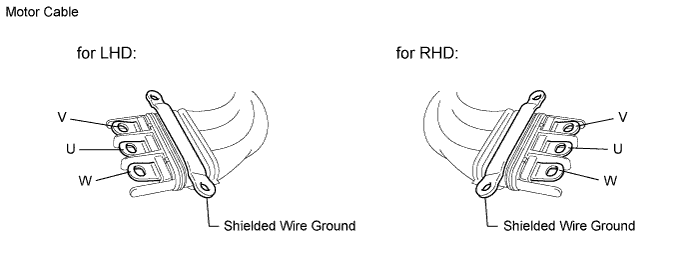
Check MG2 for an interphase short using a milliohmmeter.
-
Using a milliohmmeter, measure the resistance according to the value(s) in the table below.
Tech Tips
If the MG2 temperature is high, the resistance will vary greatly from the specification. Therefore, measure the resistance at least 8 hours after the vehicle is stopped.
Standard resistance LHD Tester Connection Switch Condition Specified Condition U - V Power switch off 46.9 to 51.8 mΩ V - W Power switch off 47.1 to 52.1 mΩ W - U Power switch off 46.8 to 51.8 mΩ RHD Tester Connection Switch Condition Specified Condition U - V Power switch off 47.2 to 52.2 mΩ V - W Power switch off 47.4 to 52.4 mΩ W - U Power switch off 47.2 to 52.1 mΩ Tech Tips
-
To correct the variation of the measured resistance due to temperature, use the following formula to calculate the resistance at 20°C (68° F).
-
R20 = Rt / {1 + 0.00393 X (T - 20)}
-
The calculation is based on the following:
-
R20: Resistance at 20°C (68° F) (mΩ)
-
Rt: Measured resistance (mΩ)
-
T: Temperature when the resistance is measured (° C)
-
-
-
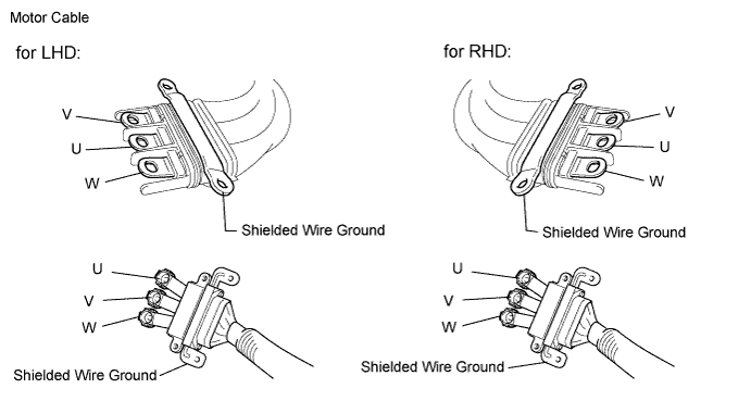
Using a megohmmeter set to 500 V, measure the resistance according to the value(s) in the table below.
Note
Be sure to set the megohmmeter to 500 V when performing this test. Using a setting higher than 500 V can result in damage to the component being inspected.
Standard resistance Tester Connection Switch Condition Specified Condition U - Body ground and shielded wire ground Power switch off 100 MΩ or higher V - Body ground and shielded wire ground Power switch off 100 MΩ or higher W - Body ground and shielded wire ground Power switch off 100 MΩ or higher
NG 
OK 
-
-
REPLACE INVERTER WITH CONVERTER ASSEMBLY
-
Replace the inverter with converter assembly Click here for LHD, Click here for RHD).
NEXT
CHECK DTC OUTPUT (HV) Click here
-
-
CHECK MOTOR CABLE
-
Remove the motor cable from the hybrid vehicle transmission assembly. Click here
-
Using a megohmmeter set to 500 V, measure the resistance according to the value(s) in the table below.
Note
Be sure to set the megohmmeter to 500 V when performing this test. Using a setting higher than 500 V can result in damage to the component being inspected.
Standard resistance Tester Connection Switch Condition Specified Condition U - Shielded wire ground Power switch off 100 MΩ or higher V - Shielded wire ground Power switch off 100 MΩ or higher W - Shielded wire ground Power switch off 100 MΩ or higher U - V Power switch off 100 MΩ or higher V - W Power switch off 100 MΩ or higher W - U Power switch off 100 MΩ or higher -
Measure the resistance according to the value(s) in the table below.
Standard resistance Tester Connection Condition Specified Condition U - U Power switch off 1 Ω or less V - V Power switch off 1 Ω or less W - W Power switch off 1 Ω or less
NG
REPLACE MOTOR CABLE Click here
OK
-
-
REPLACE HYBRID VEHICLE TRANSMISSION ASSEMBLY
-
Replace the hybrid vehicle transmission assembly Click here.
NEXT
-
-
REPLACE INVERTER WITH CONVERTER ASSEMBLY
-
Replace the inverter with converter assembly Click here for LHD, Click here for RHD).
NEXT
CHECK DTC OUTPUT (HV) Click here
-
-
REPLACE MOTOR CABLE
-
Replace the motor cable Click here.
NEXT
-
-
REPLACE INVERTER WITH CONVERTER ASSEMBLY
-
Replace the inverter with converter assembly Click here for LHD, Click here for RHD).
NEXT
-
-
CHECK DTC OUTPUT (HV)
-
Check the other DTCs that were output together with DTC P3246-202.
DTC No. Relevant Diagnosis P0A78-113, 128, 284, 286, 287, 505, 506, 806, 807, 808 Drive Motor "A" Inverter Performance Note
DTC P3246-202 is stored after any of DTCs P0A78-113, 128, 284, 286, 287, 505, 506, 806, 807 and 808 are stored. After troubleshooting and repairing DTC P3246-202, be sure to troubleshoot all the other DTCs.
NEXT 
GO TO DTC CHART Click here
-