DESCRIPTION
For a description of the inverter, (Click here).
| DTC No. | INF Code | DTC Detection Condition | Trouble Area |
|---|---|---|---|
| P3246 | 202 | Malfunction (short circuit) in the motor inverter inside the inverter with converter assembly |
|
INSPECTION PROCEDURE
-
DTC P3246-202 is stored after any of DTCs P0A78-113, 128, 284, 286, 287, 505, 506, 806, 807 and 808 are stored. After troubleshooting and repairing DTC P3246-202, be sure to troubleshoot all the other DTCs.
-
The monitor cable and hybrid vehicle transmission assembly may be affected depending on the vehicle operating conditions if a short occurs in the inverter with converter assembly. If DTC P3246-202 is output, inspect the motor cable and hybrid vehicle transmission assembly and replace the defective parts.
-
After completing the repair, test-drive the vehicle at a speed of approximately 40 km/h (25 mph) for 1 minute and check that DTC P0A90-251 (Driver Motor "A" Performance) is not output. If DTC P0A90-251 (Driver Motor "A" Performance) is output, replace the hybrid vehicle transmission assembly.
PROCEDURE
- Click here
CHECK HYBRID VEHICLE TRANSMISSION ASSEMBLY (MG2)
CAUTION:Be sure to wear insulated gloves.
-
Remove the service plug grip (Click here).
Note:After removing the service plug grip, do not turn the power switch on (READY) unless instructed by the repair manual because this may cause a malfunction.
-
Check that the service plug grip is not installed.
-
Disconnect the generator cable and motor cable from the inverter with converter assembly.
Tip:For the removal and installation procedures related to the generator cable and motor cable, (Click here).
-
Check MG2 for an interphase short using a milliohmmeter.
-
Using a milliohmmeter, measure the resistance according to the value(s) in the table below.
Tip:If the MG2 temperature is high, the resistance will vary greatly from the specification. Therefore, measure the resistance at least 8 hours after the vehicle is stopped.
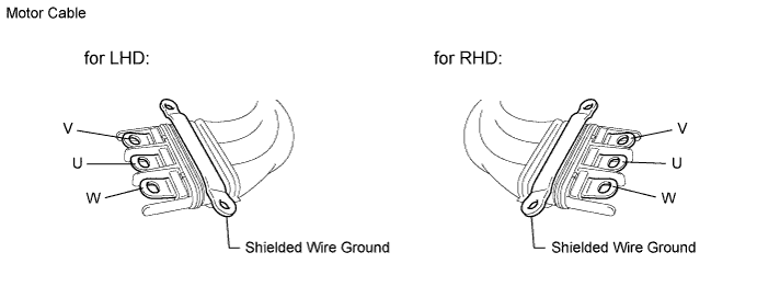
Standard resistance LHD Tester Connection Switch Condition Specified Condition U - V Power switch off 46.9 to 51.8 mΩ V - W Power switch off 47.1 to 52.1 mΩ W - U Power switch off 46.8 to 51.8 mΩ RHD Tester Connection Switch Condition Specified Condition U - V Power switch off 47.2 to 52.2 mΩ V - W Power switch off 47.4 to 52.4 mΩ W - U Power switch off 47.2 to 52.1 mΩ Tip:
-
To correct the variation of the measured resistance due to temperature, use the following formula to calculate the resistance at 20°C (68° F).
-
-
R20 = Rt / {1 + 0.00393 X (T - 20)}
-
-
The calculation is based on the following:
-
-
R20: Resistance at 20°C (68° F) (mΩ)
-
Rt: Measured resistance (mΩ)
-
T: Temperature when the resistance is measured (° C)
-
-
-
-
Using a megohmmeter set to 500 V, measure the resistance according to the value(s) in the table below.
Note:Be sure to set the megohmmeter to 500 V when performing this test. Using a setting higher than 500 V can result in damage to the component being inspected.
Standard resistance Tester Connection Switch Condition Specified Condition U - Body ground and shielded wire ground Power switch off 100 MΩ or higher V - Body ground and shielded wire ground Power switch off 100 MΩ or higher W - Body ground and shielded wire ground Power switch off 100 MΩ or higher
- OKClick here
- NGClick here
-
- Click here
REPLACE INVERTER WITH CONVERTER ASSEMBLY
-
Replace the inverter with converter assembly (Click herefor LHD,Click herefor RHD).
- NEXTClick here
-
- Click here
CHECK MOTOR CABLE
-
Remove the motor cable from the hybrid vehicle transmission assembly. (Click here)
-
Using a megohmmeter set to 500 V, measure the resistance according to the value(s) in the table below.
Note:Be sure to set the megohmmeter to 500 V when performing this test. Using a setting higher than 500 V can result in damage to the component being inspected.
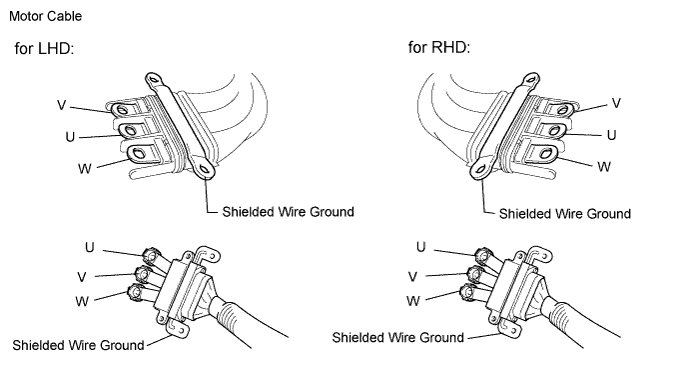
Standard resistance Tester Connection Switch Condition Specified Condition U - Shielded wire ground Power switch off 100 MΩ or higher V - Shielded wire ground Power switch off 100 MΩ or higher W - Shielded wire ground Power switch off 100 MΩ or higher U - V Power switch off 100 MΩ or higher V - W Power switch off 100 MΩ or higher W - U Power switch off 100 MΩ or higher -
Measure the resistance according to the value(s) in the table below.
Standard resistance Tester Connection Condition Specified Condition U - U Power switch off 1 Ω or less V - V Power switch off 1 Ω or less W - W Power switch off 1 Ω or less
- OKClick here
- NGClick here
-
- Click here
REPLACE HYBRID VEHICLE TRANSMISSION ASSEMBLY
-
Replace the hybrid vehicle transmission assembly (Click here).
- NEXTClick here
-
- Click here
REPLACE INVERTER WITH CONVERTER ASSEMBLY
-
Replace the inverter with converter assembly (Click herefor LHD,Click herefor RHD).
- NEXTClick here
-
- Click here
REPLACE MOTOR CABLE
-
Replace the motor cable (Click here).
- NEXTClick here
-
- Click here
REPLACE INVERTER WITH CONVERTER ASSEMBLY
-
Replace the inverter with converter assembly (Click herefor LHD,Click herefor RHD).
- NEXTClick here
-
- Click here
CHECK DTC OUTPUT (HV)
-
Check the other DTCs that were output together with DTC P3246-202.
DTC No. Relevant Diagnosis P0A78-113, 128, 284, 286, 287, 505, 506, 806, 807, 808 Drive Motor "A" Inverter Performance Note:DTC P3246-202 is stored after any of DTCs P0A78-113, 128, 284, 286, 287, 505, 506, 806, 807 and 808 are stored. After troubleshooting and repairing DTC P3246-202, be sure to troubleshoot all the other DTCs.
- NEXTClick here
-
- Click here
GO TO DTC CHARTClick here