COOLANT (for Inverter) REPLACEMENT

-
REMOVE ENGINE ROOM SIDE COVER RH
-
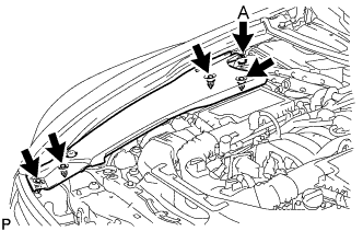
for LHD:
Remove the 5 clips and engine room side cover RH.
Note
Remove the clip labeled A by turning it to prevent the engine room side cover RH and bracket from being damaged.
Tech Tips
The clip labeled A cannot be removed from the engine room side cover RH.
-
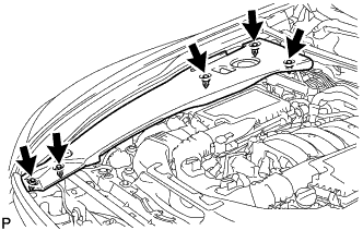
for RHD:
Remove the 5 clips and engine room side cover RH.
-
-
REMOVE ENGINE ROOM SIDE COVER LH
-
for LHD:
Remove the 5 clips and engine room side cover LH.
-
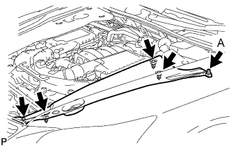
for RHD:
Remove the 5 clips and engine room side cover LH.
Note
Remove the clip labeled A by turning it to prevent the engine room side cover LH and bracket from being damaged.
Tech Tips
The clip labeled A cannot be removed from the engine room side cover LH.
-
-
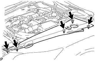
REMOVE FRONT CENTER FLOOR COVER
-
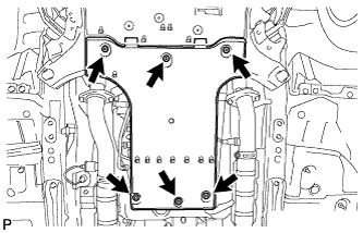
Remove the 3 screws, 2 bolts, clip and front center floor cover.
-
-
DRAIN COOLANT (for Inverter)
Note
-
Do not reuse the drained coolant because it may contain foreign objects.
-
Collect the drained coolant and measure its volume to establish a benchmark. When adding coolant, make sure to add more coolant than the measured amount.
-
Remove the inverter reserve tank cap.
CAUTION:
To avoid the danger of being burned, do not remove the inverter reserve tank cap while the coolant for the inverter is still hot.
Note
Do not remove the plug from the tube.
-
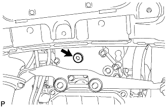
Using a hexagon wrench 10 mm, remove the drain plug indicated in the illustration and drain the coolant.
CAUTION:
Use caution when handling coolant immediately after driving or in summer because it may be hot.
-
Using a hexagon wrench 10 mm, install the drain plug with a new gasket.
- Torque:
- 39 N*m { 400 kgf*cm, 29 ft.*lbf }
-
Measure the volume of the drained coolant.
-
-
ADD COOLANT (for Inverter)
Note
-
Do not reuse the drained coolant because it may contain foreign objects.
-
If the vehicle is driven with air in the inverter cooling system, the following DTCs may be set.
DTC Code Detection Item P0A01-725 Motor Electronics Coolant Temperature Sensor Circuit Range / Performance P0A01-726 Motor Electronics Coolant Temperature Sensor Circuit Range / Performance P0A78-284 Drive Motor "A" Inverter Performance P0A7A-322 Generator Inverter Performance P0A93-346 Inverter Cooling System Performance P0A94-553 DC / DC Converter Performance P0AEE-276 Motor Inverter Temperature Sensor "A" Circuit Range / Performance P0AEE-277 Motor Inverter Temperature Sensor "A" Circuit Range / Performance P3221-314 Generator Inverter Temperature Sensor Circuit Range / Performance P3221-315 Generator Inverter Temperature Sensor Circuit Range / Performance P3226-562 DC/DC Boost Converter Temperature Sensor P3226-563 DC/DC Boost Converter Temperature Sensor
Tech Tips
-
for LHD:
Coolant (for inverter) capacity: 2.6 liters (2.7 US qts, 2.3 Imp. qts.)
-
for RHD:
Coolant (for inverter) capacity: 2.5 liters (2.5 US qts, 2.2 Imp. qts.)
-
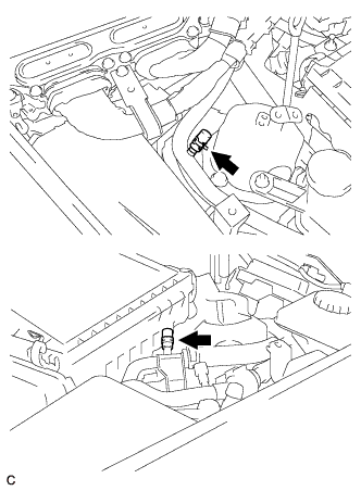
for LHD:
Remove the 2 clips and 2 plugs from the tubes.
Note
Do not reuse the clips or plugs.
-
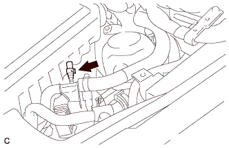
for RHD:
Remove the clip and plug from the tube.
Note
Do not reuse the clip or plug.
-
Add coolant to the reserve tank.
-
for LHD:
Install 2 new plugs and 2 new clips to the tubes.
-
for RHD:
Install a new plug and new clip to the tube.
-
Connect the intelligent tester to the DLC3.
-
Select the following menu items: Powertrain / Hybrid Control / Active Test / Activate the Water Pump.
Tech Tips
The water pump can also be operated using inspection mode Click here.
-
While adding coolant so that the coolant level is kept around the FULL line of the inverter reserve tank, operate the water pump for 3 minutes or more and then stop it for 1 minute or more.
-
While adding coolant so that the coolant level is kept around the FULL line of the inverter reserve tank, operate the water pump for 1 minute or more and stop it for 1 minute or more. Repeat this procedure until bleeding is completed.
Standard When the operation sound of the water pump becomes small or when no air bubbles can be seen in the inverter reserve tank, bleeding of the coolant system is complete. Tech Tips
-
If the water pump operates without a sufficient amount of coolant for approximately 5 seconds, the protective circuit will activate to stop the water pump for approximately 15 seconds. If a sufficient amount of coolant is added, the water pump will start operating automatically.
-
If an excessive amount of coolant is added to the inverter reserve tank, coolant may overflow when operation of the water pump is stopped.
-
-
After bleeding is completed, add coolant to the FULL level, and install the inverter reserve tank cap.
Note
Make sure to add more coolant than was drained initially.
-
-
INSPECT FOR COOLANT LEAK (for Inverter)
-
Remove the reserve tank cap.
CAUTION:
To avoid the danger of being burned, do not remove the reserve tank cap while the coolant for the inverter is still hot.
-
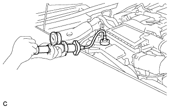
Install the radiator cap tester.
-
Pump the radiator cap tester to 37 kPa (0.38 kgf/ cm2, 5.4 psi), and then check that the pressure does not drop.
Tech Tips
If the pressure drops, check the hoses, radiator, water pump, inverter with converter, and hybrid vehicle transaxle assembly for leakage.
-
Reinstall the reserve tank cap.
-
-
INSTALL FRONT CENTER FLOOR COVER
-
Install the front center floor cover with the 3 screws, 2 bolts and clip.
- Torque:
- 5.4 N*m { 55 kgf*cm, 48 in.*lbf }
-
-
INSTALL ENGINE ROOM SIDE COVER LH
-
Install the engine room side cover LH with the 5 clips.
-
-
INSTALL ENGINE ROOM SIDE COVER RH
-
Install the engine room side cover RH with the 5 clips.
-