HYBRID CONTROL SYSTEM Shift Paddle Switch Circuit
DESCRIPTION
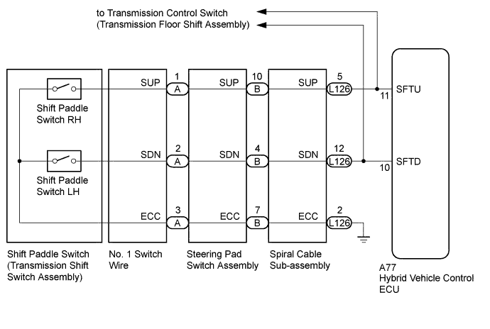
By operating the transmission shift switch of the steering pad switch assembly, the shift range can be changed and the engine braking power can be selected.
WIRING DIAGRAM
INSPECTION PROCEDURE
PROCEDURE
-
CHECK HARNESS AND CONNECTOR (SPIRAL CABLE SUB-ASSEMBLY - HYBRID VEHICLE CONTROL ECU)
-
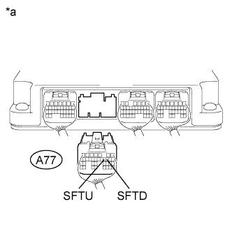
Text in Illustration *a Rear view of wire harness connector
(to Hybrid Vehicle Control ECU)
Disconnect the hybrid vehicle control ECU connector.
-
Disconnect the transmission control switch connector.
-
Measure the resistance according to the value(s) in the table below when the paddle shift is moved to each position.
Standard Resistance Tester Connection Condition Specified Condition A77-11 (SFTU) - Body ground Pull continuously
"+"
(Up shift)
Below 2.5 Ω A77-10 (SFTD) - Body ground Pull continuously
"-"
(Down shift)
Below 2.5 Ω A77-11 (SFTU) - Body ground Release
"+"
(Up shift)
1 MΩ or higher A77-10 (SFTD) - Body ground Release
"-"
(Down shift)
1 MΩ or higher -
Connect the hybrid vehicle control ECU connector.
-
Connect the transmission control switch connector.
NG 
CHECK HARNESS AND CONNECTOR (SPIRAL CABLE SUB-ASSEMBLY - BODY GROUND) Click here
OK 
REPLACE HYBRID VEHICLE CONTROL ECU Click here
-
-
CHECK HARNESS AND CONNECTOR (SPIRAL CABLE SUB-ASSEMBLY - BODY GROUND)
-
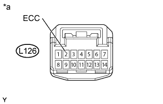
Text in Illustration *a Front view of wire harness connector
(to Spiral Cable Sub-assembly)
Disconnect the spiral cable sub-assembly connector.
-
Measure the resistance according to the value(s) in the table below.
Standard Resistance Tester Connection Condition Specified Condition L126-2 (ECC) - Body ground Always Below 1 Ω -
Connect the spiral cable sub-assembly connector.
NG 
REPAIR OR REPLACE HARNESS OR CONNECTOR
OK 
-
-
INSPECT SPIRAL CABLE SUB-ASSEMBLY
-
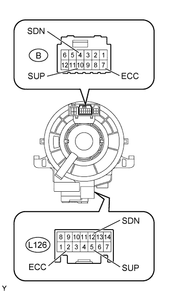
Text in Illustration *a Component without harness connected
(Spiral Cable Sub-assembly)
Remove the spiral cable sub-assembly Click here.
-
Set the spiral cable sub-assembly to the center position.
-
Measure the resistance between the terminals of the spiral cable sub-assembly according to the value(s) in the table below.
-
After setting the spiral cable sub-assembly to the center position, rotate the spiral cable sub-assembly 2.5 times clockwise and measure the resistance. Then rotate the spiral cable sub-assembly 2.5 times counterclockwise and measure the resistance.
-
After setting the spiral cable sub-assembly to the center position, rotate the spiral cable sub-assembly 2.5 times clockwise. Then while rotating the spiral cable sub-assembly 5 times counterclockwise, measure the resistance.
Standard Resistance Tester Connection Condition Specified Condition B-10 (SUP) - L126-5 (SUP) Always Below 1 Ω B-4 (SDN) - L126-12 (SDN) Always Below 1 Ω B-7 (ECC) - L126-2 (ECC) Always Below 1 Ω Note
As the spiral cable sub-assembly may break, do not rotate the spiral cable sub-assembly more than the specified amount.
-
-
Install the spiral cable sub-assembly connector.
NG
REPLACE SPIRAL CABLE SUB-ASSEMBLY Click here
OK
-
-
INSPECT TRANSMISSION SHIFT SWITCH ASSEMBLY LH
-
Text in Illustration *a Component without harness connected
(Transmission Shift Switch Assembly LH)
Remove the transmission shift switch LH Click here.
-
Measure the resistance according to the value(s) in the table below when the paddle shift is moved to each position.
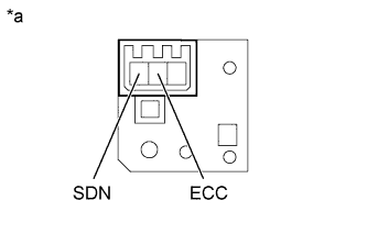
Standard Resistance Tester Connection Condition Specified Condition SDN - ECC Pull continuously
"-"
(Down shift)
Below 2.5 Ω SDN - ECC Release
"-"
(Down shift)
1 MΩ or higher -
Install the transmission shift switch LH.
NG
REPLACE TRANSMISSION SHIFT SWITCH ASSEMBLY LH Click here
OK
-
-
INSPECT TRANSMISSION SHIFT SWITCH ASSEMBLY RH
-
Text in Illustration *a Component without harness connected
(Transmission Shift Switch Assembly RH)
Remove the transmission shift switch RH Click here.
-
Measure the resistance according to the value(s) in the table below when the paddle shift is moved to each position.
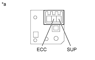
Standard Resistance Tester Connection Condition Specified Condition SUP - ECC Pull continuously
"+"
(Up shift)
Below 2.5 Ω SUP - ECC Release
"+"
(Up shift)
1 MΩ or higher -
Install the transmission shift switch RH.
NG
REPLACE TRANSMISSION SHIFT SWITCH ASSEMBLY RH Click here
OK
-
-
INSPECT NO. 1 SWITCH WIRE
-
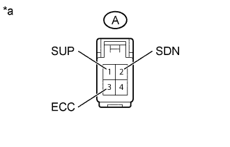
Text in Illustration *a Component without harness connected
(No. 1 Switch Wire)
Disconnect the No. 1 switch wire connector.
-
Measure the resistance according to the value(s) in the table below when the paddle shift is moved to each position.
Standard Resistance Tester Connection Condition Specified Condition A-2 (SDN) - A-3 (ECC) Pull continuously
"-"
(Down shift)
Below 2.5 Ω A-1 (SUP) - A-3 (ECC) Pull continuously
"+"
(Up shift)
Below 2.5 Ω A-2 (SDN) - A-3 (ECC) Release
"-"
(Down shift)
1 MΩ or higher A-1 (SUP) - A-3 (ECC) Release
"+"
(Up shift)
1 MΩ or higher -
Connect the No. 1 switch wire connector.
NG
REPLACE NO. 1 SWITCH WIRE Click here
OK
-
-
INSPECT STEERING PAD SWITCH ASSEMBLY
-
Disconnect the steering pad switch assembly connector.
-
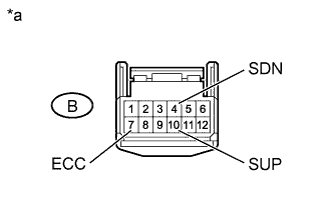
Text in Illustration *a Component without harness connected
(Steering Pad Switch Assembly)
Measure the resistance according to the value(s) in the table below when the paddle shift is moved to each position.
Standard Resistance Tester Connection Condition Specified Condition B-10 (SUP) - B-7 (ECC) Pull continuously
"+"
(Up shift)
Below 2.5 Ω B-4 (SDN) - B-7 (ECC) Pull continuously
"-"
(Down shift)
Below 2.5 Ω B-10 (SUP) - B-7 (ECC) Release
"+"
(Up shift)
1 MΩ or higher B-4 (SDN) - B-7 (ECC) Release
"-"
(Down shift)
1 MΩ or higher -
Connect the steering pad switch assembly connector.
NG
REPLACE STEERING PAD SWITCH ASSEMBLY Click here
OK
CHECK FOR INTERMITTENT PROBLEMS Click here
-