HYBRID CONTROL SYSTEM, Diagnostic DTC:P3004-803

| DTC Code | DTC Name |
|---|---|
| P3004-803 | Power Cable Malfunction |
DESCRIPTION
Refer to the description for DTC P0AE6-225 Click here.
| DTC No. | INF Code | DTC Detection Condition | Trouble Area |
|---|---|---|---|
| P3004 | 803 | While the power switch is on (READY), the electric battery fuse in the service plug grip is burned out, the service plug grip is removed, or SMRB or SMRG is open. |
|
INSPECTION PROCEDURE
CAUTION:
-
Before inspecting the high-voltage system or disconnecting the low voltage connector of the inverter with converter assembly, take safety precautions such as wearing insulated gloves and removing the service plug grip to prevent electrical shocks. After removing the service plug grip, put it in your pocket to prevent other technicians from accidentally reconnecting it while you are working on the high-voltage system.
-
After disconnecting the service plug grip, wait for at least 10 minutes before touching any of the high-voltage connectors or terminals. After waiting for 10 minutes, check the voltage at the terminals in the inspection point in the inverter with converter assembly. The voltage should be 0 V before beginning work.
Tech Tips
Waiting for at least 10 minutes is required to discharge the high-voltage capacitor inside the inverter with converter assembly.
PROCEDURE
-
CHECK DTC OUTPUT (HV)
-
Connect the intelligent tester to the DLC3.
-
Turn the power switch on (IG).
-
Select the following menu items: Powertrain / Hybrid Control / Trouble Codes.
-
Check if DTCs are output.
Result Result Proceed to P3004-803 only is output. A Any of the following DTCs are also output. B DTC No. Relevant Part P0A1A-151, 155, 156, 658, 659 Generator Control Module P0A1B-163, 164, 193, 511, 512, 786, 788, 661 Drive Motor "A" Control Module P0A78-266, 267, 586 Drive Motor "A" Inverter Performance P0A94-442 DC / DC Converter Performance P0A95-123 High Voltage Fuse P0ADC-226 Hybrid Battery Positive Contactor Control Circuit High P0ADB-227 Hybrid Battery Positive Contactor Control Circuit Low P0ADF-229 Hybrid Battery Negative Contactor Control Circuit Low P0AE0-228 Hybrid Battery Negative Contactor Control Circuit High P0AFA-123 Hybrid Battery System Voltage Low P0C76-523 Hybrid Battery System Discharge Time Too Long P3004-131 Power Cable Malfunction P3240-443 DC / DC Converter Control Circuit
B 
GO TO DTC CHART Click here
A 
-
-
CLEAR DTC (HV)
-
Select the following menu items: Powertrain / Hybrid Control / Trouble Codes.
-
Read and record the DTCs and freeze frame data.
-
Select the following menu items: Powertrain / Hybrid Control / Trouble Codes.
-
Clear DTCs and freeze frame data.
NEXT
-
-
CHECK DTC OUTPUT (HV)
-
Turn the power switch on (READY).
-
Move the shift lever to the D position and depress both the accelerator pedal and brake pedal at the same time.
Note
Make sure the areas in front and at the back of the vehicle are safe.
Tech Tips
-
Depressing both the accelerator pedal and brake pedal at the same time causes the HV battery current to flow and ensures that there is no problem with the high-voltage wiring.
-
Depressing both the accelerator pedal and brake pedal at the same time causes ACCEL AND BRK in the inappropriate operation and history data to be incremented.
-
-
Select the following menu items: Powertrain / Hybrid Control / Trouble Codes.
-
Check if DTCs are output.
Result Result Proceed to P3004-803 is output, or no DTCs are output. A Power switch is not turned on (READY) and P3004-131 is output. B
B
GO TO DTC CHART (P3004-131) Click here
A
-
-
CHECK CONNECTOR CONNECTION CONDITION (HYBRID VEHICLE CONTROL ECU CONNECTOR)
-
Check the connections of the hybrid vehicle control ECU connectors.
Result The connectors are connected securely and there are no contact problems.
NG
CONNECT SECURELY
OK
-
-
CHECK HARNESS AND CONNECTOR (HYBRID VEHICLE CONTROL ECU - NO. 1 BATTERY PACK WIRE CONNECTOR)
-
Disconnect connector E58 from the hybrid vehicle control ECU.
-
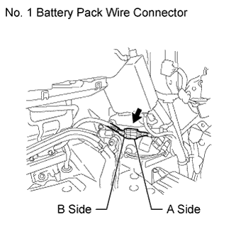
Disconnect the No. 1 battery pack wire connector.
Tech Tips
Due to the time required to disconnect the HV battery junction block and hybrid vehicle converter connectors, the No. 1 battery pack wire connector resistance check should be performed before these connectors are disconnected.
-
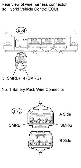
Measure the resistance according to the value(s) in the table below.
Standard resistance Tester Connection Switch Condition Specified Condition E58-5 (SMRB) - zR3-5 (SMRB) Power switch off Below 1 Ω E58-4 (SMRG) - zR3-4 (SMRG) Power switch off Below 1 Ω
NG
REPAIR OR REPLACE HARNESS OR CONNECTOR
OK
-
-
CHECK HARNESS AND CONNECTOR (NO. 1 BATTERY PACK WIRE CONNECTOR - HV BATTERY JUNCTION BLOCK)
CAUTION:
Be sure to wear insulated gloves.
-
Turn the power switch off.
-
Remove the service plug grip Click here.
Note
After removing the service plug grip, do not turn the power switch on (READY) unless instructed by the repair manual because this may cause a malfunction.
-
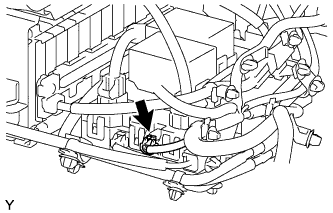
Disconnect the low voltage connector that drives the relay of the HV battery junction block.
Tech Tips
For the removal and installation procedures related to the HV battery junction block connector, Click here.
-
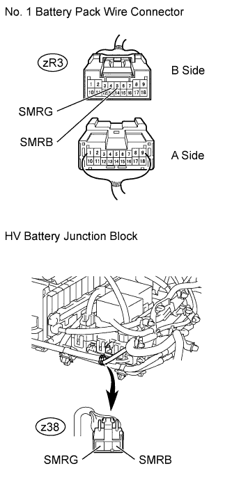
Measure the resistance according to the value(s) in the table below.
Standard resistance Tester Connection Switch Condition Specified Condition zR3-5 (SMRB) - z38-3 (SMRB) Power switch off Below 1 Ω zR3-4 (SMRG) - z38-1 (SMRG) Power switch off Below 1 Ω
NG
REPAIR OR REPLACE HARNESS OR CONNECTOR
OK 
REPLACE HV BATTERY JUNCTION BLOCK Click here
-