HYBRID CONTROL SYSTEM, Diagnostic DTC:P3110-223

| DTC Code | DTC Name |
|---|---|
| P3110-223 | IGCT Relay Malfunction |
DESCRIPTION
The hybrid vehicle control ECU monitors the ST CUT/IGCT2 relay and detects the following malfunction.
| DTC No. | INF Code | DTC Detection Condition | Trouble Area |
|---|---|---|---|
| P3110 | 223 | There is a short to +B in the IGCT2 relay or the ST CUT/IGCT2 relay is stuck closed. |
|
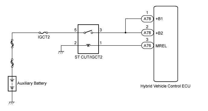
WIRING DIAGRAM
INSPECTION PROCEDURE
Tech Tips
If the battery voltage is applied to terminal +B1 or +B2 of the hybrid vehicle control ECU, even though the power switch is off, the circuit is shorted to +B.
PROCEDURE
-
CHECK DTC OUTPUT (HV)
-
Connect the intelligent tester to the DLC3.
-
Turn the power switch on (IG).
-
Move the shift lever to a position other than P.
-
Leave the vehicle as is for approximately 1 second.
-
Select the following menu items: Powertrain / Hybrid Control / Trouble Codes.
-
Check if DTCs are output.
Result Result Proceed to P3110-223 only is output. A Any of the following DTCs are also output. B DTC No. Relevant Diagnosis P0705-757 Transmission Range Sensor Circuit P0851-775 Park / Neutral Switch Input Circuit Low P0867-882 Transmission Fluid Pressure P2721-853 Pressure Control Solenoid Circuit High Voltage -
Move the shift lever to P position.
B 
GO TO DTC CHART Click here
A 
-
-
CHECK RELAY (ST CUT/IGCT2 RELAY)
-
Turn the power switch off.
-
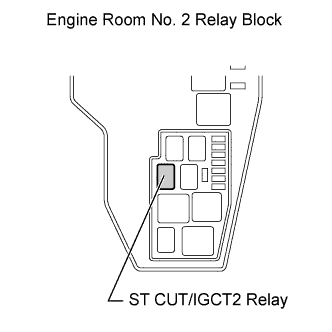
Remove the ST CUT/IGCT2 relay from the engine room No. 2 relay block.
-
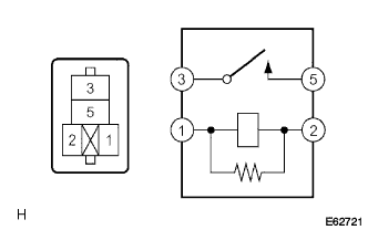
Measure the resistance according to the value(s) in the table below.
Standard resistance Tester Connection Condition Specified Condition 3 - 5 Battery voltage is not applied between terminal 1 and 2. 10 kΩ or higher
NG
REPLACE RELAY (ST CUT/IGCT2 RELAY)
OK
-
-
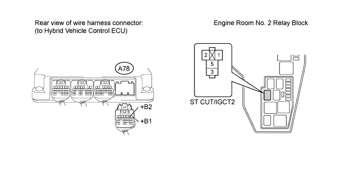
CHECK HARNESS AND CONNECTOR (HYBRID VEHICLE CONTROL ECU - ENGINE ROOM NO. 2 RELAY BLOCK)
-
Disconnect connector A78 from the hybrid vehicle control ECU.
-
Turn the power switch on (IG).
-
Measure the voltage according to the value(s) in the table below.
Note
Turning the power switch on (IG) with the hybrid vehicle control ECU connector disconnected causes other DTCs to be stored. Clear the DTCs after performing this inspection.
Standard voltage Tester Connection Condition Specified Condition A78-1 (+B1), A78-2 (+B2) or Engine room No. 2 relay block Terminal 3 - Body ground Power switch on (IG) Below 1 V
NG
REPAIR OR REPLACE HARNESS OR CONNECTOR
OK 
REPLACE HYBRID VEHICLE CONTROL ECU Click here
-