HYBRID CONTROL SYSTEM, Diagnostic DTC:P2720-852, P2721-853

| DTC Code | DTC Name |
|---|---|
| P2720-852 | Pressure Control Solenoid Circuit Low Voltage |
| P2721-853 | Pressure Control Solenoid Circuit High Voltage |
DESCRIPTION
For a description of the hybrid vehicle transmission assembly, Click here.
| DTC No. | INF Code | DTC Detection Condition | Trouble Area |
|---|---|---|---|
| P2720 | 852 | Short in the SP solenoid valve circuit |
|
| P2721 | 853 | Open or short to +B in the SP solenoid valve circuit |
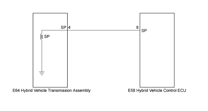
WIRING DIAGRAM
INSPECTION PROCEDURE
PROCEDURE
-
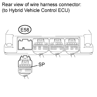
CHECK CONNECTOR CONNECTION CONDITION (HYBRID VEHICLE CONTROL ECU CONNECTOR)
-
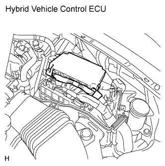
Check the connections of the hybrid vehicle control ECU connectors.
OK The connectors are connected securely and there are no contact problems.
NG 
CONNECT SECURELY
OK 
-
-
CHECK HYBRID VEHICLE TRANSMISSION ASSEMBLY (SP SOLENOID)
-
Turn the power switch off.
-
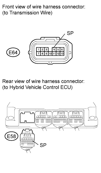
Disconnect connector E58 from the hybrid vehicle control ECU.
-
Turn the power switch on (IG).
Note
Turning the power switch on (IG) with the hybrid vehicle control ECU connector disconnected causes other DTCs to be stored. Clear the DTCs after performing this inspection.
-
Measure the voltage according to the value(s) in the table below.
Standard voltage Tester Connection Switch Condition Specified Condition E58-8 (SP) - Body ground Power switch on (IG) Below 1 V -
Turn the power switch off.
-
Measure the resistance according to the value(s) in the table below.
Standard resistance (Check for open) Tester Connection Switch Condition Specified Condition E58-8 (SP) - Body ground Power switch off
(-10°C (14° F))
11.47 Ω
(Reference)
Power switch off
(20°C (68° F))
11 to 15 Ω Power switch off
(80°C (176° F))
16.06 Ω
(Reference)
Power switch off
(120°C (248° F))
18.11 Ω
(Reference)
Standard resistance (Check for short) Tester Connection Switch Condition Specified Condition E58-8 (SP) - Body ground and other terminals Power switch off 10 kΩ or higher
NG 
CHECK CONNECTOR CONNECTION CONDITION (TRANSMISSION WIRE CONNECTOR) Click here
OK
-
-
CHECK FOR INTERMITTENT PROBLEMS
-
Check for intermittent problems Click here.
NG
REPAIR OR REPLACE MALFUNCTIONING PARTS, COMPONENT AND AREA
OK 
REPLACE HYBRID VEHICLE CONTROL ECU Click here
-
-
CHECK CONNECTOR CONNECTION CONDITION (TRANSMISSION WIRE CONNECTOR)
-
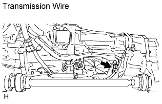
Check the connection of the transmission wire connector.
OK The connector is connected securely and there are no contact problems.
NG
CONNECT SECURELY
OK
-
-
CHECK HARNESS AND CONNECTOR (TRANSMISSION WIRE - HYBRID VEHICLE CONTROL ECU)
-
Disconnect the transmission wire connector.
-
Turn the power switch on (IG).
-
Measure the voltage according to the value(s) in the table below.
Standard voltage Tester Connection Switch Condition Specified Condition E58-8 (SP) - Body ground Power switch on (IG) Below 1 V Note
Turning the power switch on (IG) with the hybrid vehicle control ECU connector disconnected causes other DTCs to be stored. Clear the DTCs after performing this inspection.
-
Turn the power switch off.
-
Measure the resistance according to the value(s) in the table below.
Standard resistance (Check for open) Tester Connection Switch Condition Specified Condition E58-8 (SP) - E64-4 (SP) Power switch off Below 1 Ω Standard resistance (Check for short) Tester Connection Switch Condition Specified Condition E58-8 (SP) or E64-4 (SP) - Body ground and other terminals Power switch off 10 kΩ or higher Tech Tips
The SP solenoid valve is not available separately. If it requires replacement, replace the hybrid vehicle transmission assembly.
NG
REPAIR OR REPLACE HARNESS OR CONNECTOR
OK
REPLACE HYBRID VEHICLE TRANSMISSION ASSEMBLY Click here
-