HYBRID CONTROL SYSTEM, Diagnostic DTC:P2532-772

| DTC Code | DTC Name |
|---|---|
| P2532-772 | Ignition Switch Run Position Circuit High |
DESCRIPTION
The hybrid vehicle control ECU monitors IGSW signals sent from the power source control ECU and detects the following malfunction.
| DTC No. | INF Code | DTC Detection Condition | Trouble Area |
|---|---|---|---|
| P2532 | 772 | When IG1 information from the ECUs that are connected to terminal IG1 of the power source control ECU is interrupted, the power source voltage is still applied to terminal IGSW. |
|
Tech Tips
If DTC P2532-772 is stored, the vehicle will turn off.
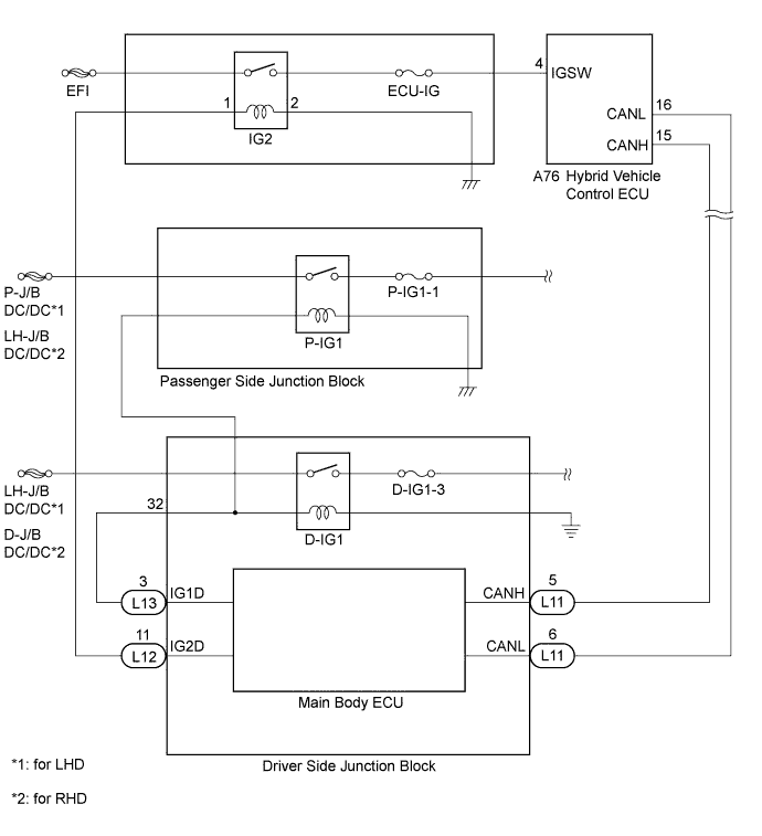
WIRING DIAGRAM
INSPECTION PROCEDURE
Tech Tips
If DTC P2532-722 is output, U0164-594, U0164-827, U0129-220, U0129-528, U0131-443, U0131-434 or U0140-146 may be output.
PROCEDURE
-
CLEAR DTC
-
Connect the intelligent tester to the DLC3.
-
Turn the power switch on (IG).
-
Select the following menu items: Powertrain / Hybrid Control / Trouble Codes.
-
Read and record the DTCs and freeze frame data.
-
Select the following menu items: Powertrain / Hybrid Control / Trouble Codes.
-
Clear DTCs and freeze frame data.
NEXT 
-
-
CHECK DTC OUTPUT (HV)
-
Leave the vehicle for 15 seconds or more with the power switch on (IG) after clearing DTCs.
Tech Tips
Leaving the vehicle for 15 seconds or more is required to detect DTC U0140-146.
-
Select the following menu items: Powertrain / Hybrid Control / Trouble Codes.
-
Check if DTCs are output.
Result Result Proceed to Either of the following is met:
-
U0140-146 is also output.
-
U0140-146 is not output but P2532-772 is output.
A U0140-146 and P2532-772 are output. B Only DTCs other than U0140-146 and P2532-772 are output. C No DTC is output. D -
B 
GO TO DTC CHART (U0140-146) Click here
C
GO TO DTC CHART Click here
D 
CHECK DTC OUTPUT (HV) Click here
A
-
-
CHECK FUSES (D-IG1-3)
-
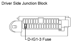
Remove the D-IG1-3 fuse from the driver side junction block.
-
Measure the resistance according to the value(s) in the table below.
Standard resistance Tester Connection Switch Condition Specified Condition D-IG1-3 Fuse Power switch off Below 1 Ω
NG
REPLACE FUSES (D-IG1-3)
OK
-
-
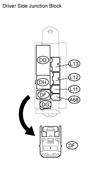
CHECK POWER SOURCE CIRCUIT (DRIVER SIDE JUNCTION BLOCK)
-
Power switch off.
-
Remove connector DF from the driver side junction block.
-
Measure the voltage according to the value(s) in the table below.
Standard voltage Tester Connection Switch Condition Specified Condition DF-1 - Body ground Power switch off 11 to 14 V
NG
REPAIR OR REPLACE HARNESS OR CONNECTOR (DRIVER SIDE JUNCTION BLOCK - AUXILIARY BATTERY)
OK
-
-
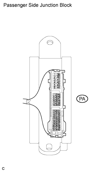
CHECK POWER SOURCE CIRCUIT (PASSENGER SIDE JUNCTION BLOCK)
-
Power switch off.
-
Connect connector PA from the passenger side junction block.
-
Power switch on (IG).
-
Measure the voltage according to the value(s) in the table below.
Standard voltage Tester Connection Switch Condition Specified Condition PA-53 - Body ground Power switch on (IG) 11 to 14 V Tech Tips
Measure the back of the connector with the connector connected.
NG
CHECK CONNECTOR CONNECTION CONDITION (PASSENGER SIDE JUNCTION BLOCK)
OK
-
-
CHECK WIRE HARNESS AND CONNECTOR
-
Power switch off.
-
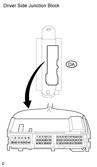
Remove connector DA from the driver side junction block.
-
Power switch on (IG).
-
Measure the voltage according to the value(s) in the table below.
Standard resistance Tester Connection Switch Condition Specified Condition DA-40 - Body ground Power switch off Below 1 Ω
NG
REPAIR OR REPLACE HARNESS OR CONNECTOR
OK 
REPLACE DRIVER SIDE JUNCTION BLOCK
-
-
CHECK DTC OUTPUT (HV)
-
Turn the power switch off.
-
Leave the vehicle for 1.5 seconds or more.
Tech Tips
Leaving the vehicle for 1.5 seconds or more is required to detect DTC P2532-772.
-
Power switch on (IG).
-
Select the following menu items: Powertrain / Hybrid Control / Trouble Codes.
-
Check if DTCs are output.
Result Result Proceed to P2532-772 is output. A P2532-772 is not output. B
B
CHECK FOR INTERMITTENT PROBLEMS Click here
A
-
-
CHECK HYBRID VEHICLE CONTROL ECU
-
Turn the power switch off.
-
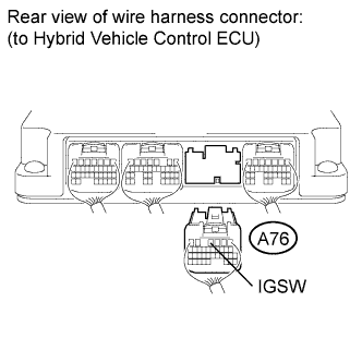
Disconnect connector A76 from the hybrid vehicle control ECU.
-
Measure the voltage according to the value(s) in the table below.
Standard voltage Tester Connection Switch Condition Specified Condition A76-4 (IGSW) - Body ground Power switch off Below 1 V
NG
CHECK RELAY (IG2 RELAY) Click here
OK
REPLACE HYBRID VEHICLE CONTROL ECU Click here
-
-
CHECK RELAY (IG2 RELAY)
-
Turn the power switch off.
-
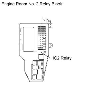
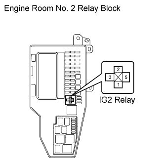
Remove the IG2 relay from the engine room No. 2 relay block.
-
Measure the voltage according to the value(s) in the table below.
Standard voltage Tester Connection Switch Condition Specified Condition A76-4 (IGSW) - Body ground Power switch off Below 1 V
NG
REPAIR OR REPLACE HARNESS OR CONNECTOR
OK
-
-
INSPECT PCV RELAY (IG2 RELAY)
-
Measure the resistance according to the value(s) in the table below.
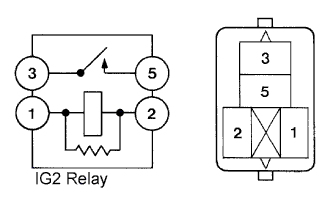
Standard resistance Tester Connection Condition Specified Condition 1 - 2 Always 130 to 235 Ω 3 - 5 Auxiliary battery voltage is not applied between terminals 1 and 2. 10 kΩ or higher Auxiliary battery voltage is applied between terminals 1 and 2. Below 1 Ω
NG
REPLACE RELAY (IG2 RELAY)
OK
-
-
CHECK HARNESS AND CONNECTOR (DRIVER SIDE JUNCTION BLOCK - IG2 RELAY)
-
Turn the power switch off.
-
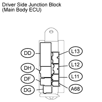
Disconnect connector L12 from the driver side junction block.
-
Measure the voltage according to the value(s) in the table below.
Standard voltage Tester Connection Switch Condition Specified Condition Engine room No. 2 relay block IG2 relay terminal 1 - Body ground Power switch off Below 1 V
NG
REPAIR OR REPLACE HARNESS OR CONNECTOR
OK
REPLACE DRIVER SIDE JUNCTION BLOCK
-