HYBRID CONTROL SYSTEM, Diagnostic DTC:P2120-152, P2121-106, P2122-104, P2123-105, P2125-153, P2126-109, P2127-107, P2128-108, P2138-110, P2138-154

| DTC Code | DTC Name |
|---|---|
| P2120-152 | Throttle / Pedal Position Sensor / Switch "D" Circuit |
| P2121-106 | Throttle / Pedal Position Sensor / Switch "D" Circuit Range / Performance |
| P2122-104 | Throttle / Pedal Position Sensor / Switch "D" Circuit Low Input |
| P2123-105 | Throttle / Pedal Position Sensor / Switch "D" Circuit High Input |
| P2125-153 | Throttle / Pedal Position Sensor / Switch "E" Circuit |
| P2126-109 | Throttle / Pedal Position Sensor / Switch "E" Circuit Range / Performance |
| P2127-107 | Throttle / Pedal Position Sensor / Switch "E" Circuit Low Input |
| P2128-108 | Throttle / Pedal Position Sensor / Switch "E" Circuit High Input |
| P2138-110 | Throttle / Pedal Position Sensor / Switch "D" / "E" Voltage Correlation |
| P2138-154 | Throttle / Pedal Position Sensor / Switch "D" / "E" Voltage Correlation |
DESCRIPTION
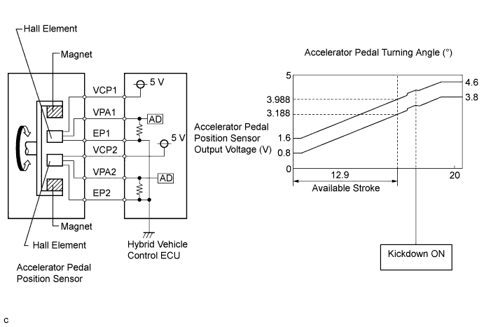
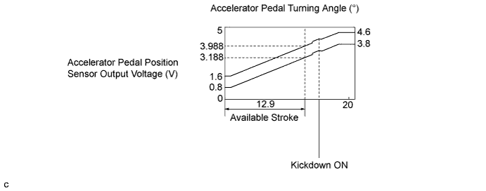
The accelerator pedal position sensor is mounted on the accelerator pedal to detect how much the pedal is depressed. This is a non-contact sensor with hall elements. There are 2 outputs from the sensor. One is used to detect the accelerator pedal position and the other is used as a confirmation to allow the detection of a malfunction in the sensor itself. Voltage is output from the accelerator pedal position sensor to terminals VPA1 and VPA2 of the hybrid vehicle control ECU. This voltage varies from 0 to 5 V in accordance with the accelerator pedal position. Terminal VPA2 is primarily used to detect a malfunction in the sensor itself. The hybrid vehicle control ECU determines the current accelerator pedal position and controls the hybrid control system based on signals received by terminals VPA1 and VPA2. The accelerator pedal position sensor also contains a kickdown circuit. When the accelerator pedal reaches a specified position, the output voltage of VPA1 and VPA2 will jump slightly higher as shown in the illustration that follows.
| DTC No. | INF Code | DTC Detection Condition | Trouble Area |
|---|---|---|---|
| P2120 | 152 | Main sensor circuit wiring malfunction or level is not stable |
|
| P2121 | 106 | Internal error of the main sensor | |
| P2122 | 104 | Open or short to GND in the main sensor circuit | |
| P2123 | 105 | Short to +B in the main sensor circuit | |
| P2125 | 153 | Sub sensor circuit wiring malfunction or level is not stable | |
| P2126 | 109 | Internal error of the sub sensor | |
| P2127 | 107 | Open or short to GND in the sub sensor circuit | |
| P2128 | 108 | Short to +B in the sub sensor circuit | |
| P2138 | 110 | Difference between the main sensor value and sub sensor value is large. | |
| P2138 | 154 | Main or sub sensor circuit wiring malfunction |
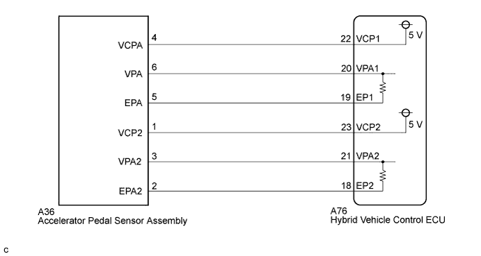
WIRING DIAGRAM
INSPECTION PROCEDURE
PROCEDURE
-
PERFORM ACTIVE TEST USING INTELLIGENT TESTER (ACCEL POS #1, ACCEL POS #2)
-
Connect the intelligent tester to the DLC3.
-
Turn the power switch on (IG).
-
Select the following menu items: Powertrain / Hybrid Control / Data List / Accel Pedal Pos #1, Accel Pedal Pos #2.
-
Read the data list.
Result Tester Display Accelerator Pedal Condition Specified Condition Accel Pedal Pos #1 Not depressed (8 to 28 %) 0.4 to 1.4 V Fully depressed (62 to 92 %) 3.1 to 4.6 V Not depressed → Fully depressed → Not depressed (Accelerator pedal should be operated slowly) Value changes progressively as shown in the illustration Accel Pedal Pos #2 Not depressed (20 to 44 %) 1.0 to 2.2 V Fully depressed (78 to 100 %) 3.9 to 5.0 V Not depressed → Fully depressed → Not depressed (Accelerator pedal should be operated slowly) Value changes progressively as shown in the illustration Tech Tips
-
5 V is described as 100% on the tester.
-
The voltage changes when kickdown occurs.
-
NG 
CHECK CONNECTOR CONNECTION CONDITION (ACCELERATOR PEDAL SENSOR ASSEMBLY CONNECTOR) Click here
OK 
CHECK FOR INTERMITTENT PROBLEMS Click here
-
-
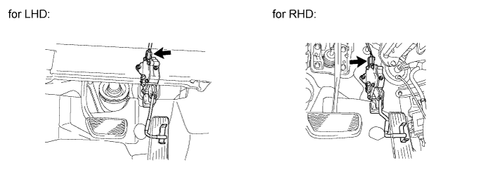
CHECK CONNECTOR CONNECTION CONDITION (ACCELERATOR PEDAL SENSOR ASSEMBLY CONNECTOR)
-
Check the connection of the accelerator pedal sensor assembly connector.
OK The connector is connected securely and there are no contact problems.
NG 
CONNECT SECURELY
OK 
-
-
CHECK CONNECTOR CONNECTION CONDITION (HYBRID VEHICLE CONTROL ECU CONNECTOR)
-
Check the connections of the hybrid vehicle control ECU connectors.
OK The connectors are connected securely and there are no contact problems.
NG
CONNECT SECURELY
OK
-
-
CHECK HYBRID VEHICLE CONTROL ECU (CHECK VOLTAGE)
-
Turn the power switch off.
-
Disconnect the accelerator pedal sensor assembly connector.
-
Turn the power switch on (IG).
-
Measure the voltage according to the value(s) in the table below.
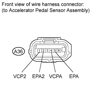
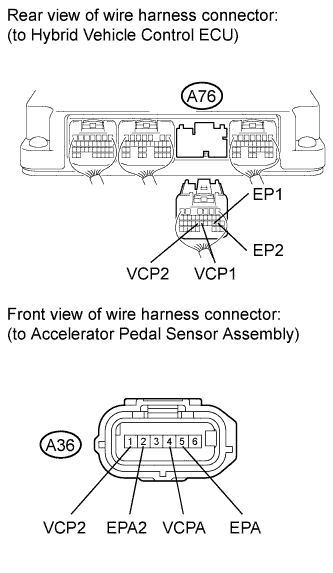
Standard voltage Tester Connection Switch Condition Specified Condition A36-4 (VCPA) - A36-5 (EPA) Power switch on (IG) 4.5 to 5.5 V A36-1 (VCP2) - A36-2 (EPA2) Power switch on (IG) 4.5 to 5.5 V
NG
CHECK HARNESS AND CONNECTOR (HYBRID VEHICLE CONTROL ECU-ACCELERATOR PEDAL SENSOR ASSEMBLY) Click here
OK
-
-
CHECK HYBRID VEHICLE CONTROL ECU (CHECK RESISTANCE)
-
Turn the power switch off.
-
Measure the resistance according to the value(s) in the table below.
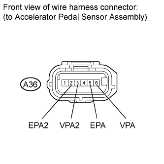
Standard resistance Tester Connection Switch Condition Specified Condition A36-6 (VPA) - A36-5 (EPA) Power switch off 36.60 to 41.61 kΩ A36-3 (VPA2) - A36-2 (EPA2) Power switch off 36.60 to 41.61 kΩ
NG
CHECK HARNESS AND CONNECTOR (HYBRID VEHICLE CONTROL ECU-ACCELERATOR PEDAL SENSOR ASSEMBLY) Click here
OK
REPLACE ACCELERATOR PEDAL SENSOR ASSEMBLY Click here
-
-
CHECK HARNESS AND CONNECTOR (HYBRID VEHICLE CONTROL ECU-ACCELERATOR PEDAL SENSOR ASSEMBLY)
-
Turn the power switch off.
-
Disconnect connector A76 from the hybrid vehicle control ECU.
-
Turn the power switch on (IG).
-
Measure the voltage according to the value(s) in the table below.
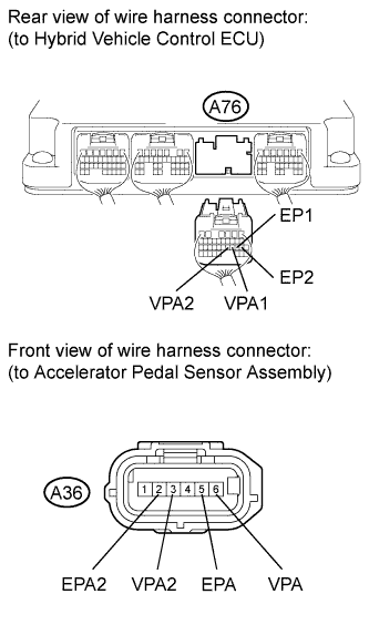
Standard voltage Tester Connection Switch Condition Specified Condition A76-20 (VPA1) - Body ground Power switch on (IG) Below 1 V A76-21 (VPA2) - Body ground Power switch on (IG) Below 1 V A76-19 (EP1) - Body ground Power switch on (IG) Below 1 V A76-18 (EP2) - Body ground Power switch on (IG) Below 1 V Note
Turning the power switch on (IG) with the hybrid vehicle control ECU connector disconnected causes other DTCs to be stored. Clear the DTCs after performing this inspection.
-
Turn the power switch off.
-
Measure the resistance according to the value(s) in the table below.
Standard resistance (Check for open) Tester Connection Switch Condition Specified Condition A76-20 (VPA1) - A36-6 (VPA) Power switch off Below 1 Ω A76-19 (EP1) - A36-5 (EPA) Power switch off Below 1 Ω A76-21 (VPA2) - A36-3 (VPA2) Power switch off Below 1 Ω A76-18 (EP2) - A36-2 (EPA2) Power switch off Below 1 Ω Standard resistance (Check for short) Tester Connection Switch Condition Specified Condition A76-20 (VPA1) or A36-6 (VPA) - Body ground and other terminals Power switch off 10 kΩ or higher A76-19 (EP1) or A36-5 (EPA) - Body ground and other terminals Power switch off 10 kΩ or higher A76-21 (VPA2) or A36-3 (VPA2) - Body ground and other terminals Power switch off 10 kΩ or higher A76-18 (EP2) or A36-2 (EPA2) - Body ground and other terminals Power switch off 10 kΩ or higher
NG
REPAIR OR REPLACE HARNESS OR CONNECTOR
OK
REPLACE HYBRID VEHICLE CONTROL ECU Click here
-
-
CHECK HARNESS AND CONNECTOR (HYBRID VEHICLE CONTROL ECU-ACCELERATOR PEDAL SENSOR ASSEMBLY)
-
Turn the power switch off.
-
Disconnect connector A76 from the hybrid vehicle control ECU.
-
Turn the power switch on (IG).
-
Measure the voltage according to the value(s) in the table below.
Standard voltage Tester Connection Switch Condition Specified Condition A76-22 (VCP1) - Body ground Power switch on (IG) Below 1 V A76-19 (EP1) - Body ground Power switch on (IG) Below 1 V A76-23 (VCP2) - Body ground Power switch on (IG) Below 1 V A76-18 (EP2) - Body ground Power switch on (IG) Below 1 V Note
Turning the power switch on (IG) with the hybrid vehicle control ECU connector disconnected causes other DTCs to be stored. Clear the DTCs after performing this inspection.
-
Turn the power switch off.
-
Measure the resistance according to the value(s) in the table below.
Standard resistance (Check for open) Tester Connection Switch Condition Specified Condition A76-22 (VCP1) - A36-4 (VCPA) Power switch off Below 1 Ω A76-19 (EP1) - A36-5 (EPA) Power switch off Below 1 Ω A76-23 (VCP2) - A36-1 (VCP2) Power switch off Below 1 Ω A76-18 (EP2) - A36-2 (EPA2) Power switch off Below 1 Ω Standard resistance (Check for short) Tester Connection Switch Condition Specified Condition A76-22 (VCP1) or A36-4 (VCPA) - Body ground and other terminals Power switch off 10 kΩ or higher A76-19 (EP1) or A36-5 (EPA) - Body ground and other terminals Power switch off 10 kΩ or higher A76-23 (VCP2) or A36-1 (VCP2) - Body ground and other terminals Power switch off 10 kΩ or higher A76-18 (EP2) or A36-2 (EPA2) - Body ground and other terminals Power switch off 10 kΩ or higher
NG
REPAIR OR REPLACE HARNESS OR CONNECTOR
OK
REPLACE HYBRID VEHICLE CONTROL ECU Click here
-