HYBRID CONTROL SYSTEM, Diagnostic DTC:P3108-535, P3108-536, P3108-538

| DTC Code | DTC Name |
|---|---|
| P3108-535 | Lost Communication with A/C System Control Module |
| P3108-536 | A/C Amplifier Communication Circuit Malfunction |
| P3108-538 | Lost Communication with A/C System Control Module |
DESCRIPTION
-
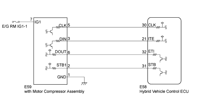
The hybrid vehicle control ECU detects a wiring malfunction in the serial communication line between it and the with motor compressor assembly.
| DTC No. | INF Code | DTC Detection Condition | Trouble Area |
|---|---|---|---|
| P3108 | 535 | Serial communication error |
|
| P3108 | 536 | A/C inverter malfunction | |
| P3108 | 538 | Open in the STB signal circuit |
WIRING DIAGRAM
INSPECTION PROCEDURE
PROCEDURE
-
CHECK DTC OUTPUT (HV)
-
Connect the intelligent tester to the DLC3.
-
Turn the power switch on (IG).
-
Select the following menu items: Powertrain / Hybrid Control / Trouble Codes.
-
Check if DTCs are output.
Result Result Proceed to P3108-535, P3108-536, or P3108-538 only is output. A Any of the following DTCs are also output. B DTC No. Relevant Diagnosis P0ADC-226 Hybrid Battery Positive Contactor Control Circuit High P0AE0-228 Hybrid Battery Negative Contactor Control Circuit High Tech Tips
DTC P3108-535 may be stored due to an open circuit in the SMRB or SMRG circuit.
B 
GO TO DTC CHART Click here
A 
-
-
CHECK CONNECTOR CONNECTION CONDITION (HYBRID VEHICLE CONTROL ECU CONNECTOR)
-
Check the connections of the hybrid vehicle control ECU connectors.
OK The connectors are connected securely and there are no contact problems.
NG
CONNECT SECURELY
OK
-
-
CHECK CONNECTOR CONNECTION CONDITION (WITH MOTOR COMPRESSOR ASSEMBLY CONNECTOR)
-
Check the connection of the low voltage connector of the with motor compressor assembly.
OK The connector is connected securely and there are no contact problems.
NG
CONNECT SECURELY
OK
-
-
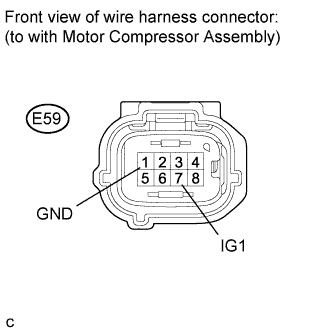
CHECK HARNESS AND CONNECTOR (WITH MOTOR COMPRESSOR ASSEMBLY)
-
Turn the power switch off.
-
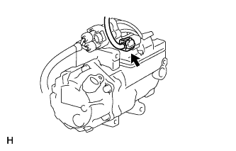
Disconnect the with motor compressor assembly connector.
-
Measure the resistance according to the value(s) in the table below.
Standard resistance Tester Connection Switch Condition Specified Condition E59-1 (GND) - Body ground Power switch off Below 1 Ω -
Turn the power switch on (IG).
-
Measure the voltage according to the value(s) in the table below.
Standard voltage Tester Connection Switch Condition Specified Condition E59-7 (IG1) - E59-1 (GND) Power switch on (IG) 10 to 14 V Note
Turning the power switch on (IG) with the with motor compressor assembly connector disconnected causes other DTCs to be stored. Clear the DTCs after performing this inspection.
NG
REPAIR OR REPLACE HARNESS OR CONNECTOR
OK
-
-
CHECK DTC OUTPUT (HV)
-
Turn the power switch off.
-
Connect the with motor compressor assembly connector.
-
Connect the intelligent tester to the DLC3.
-
Turn the power switch on (READY).
-
Select the following menu items: Powertrain / Hybrid Control / Trouble Codes.
-
Check if DTCs are output.
Result Result Proceed to P3108-535 is output. A P3108-535 is not output and P3108-538 is output. B P3108-538 is not output and P3108-536 is output. A
B 
CHECK HARNESS AND CONNECTOR (HYBRID VEHICLE CONTROL ECU - WITH MOTOR COMPRESSOR ASSEMBLY) Click here
A
-
-
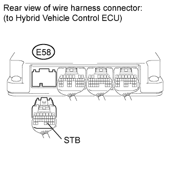
CHECK HARNESS AND CONNECTOR (HYBRID VEHICLE CONTROL ECU - WITH MOTOR COMPRESSOR ASSEMBLY)
-
Turn the power switch off.
-
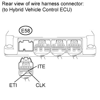
Disconnect connector E58 from the hybrid vehicle control ECU.
-
Disconnect the with motor compressor assembly connector.
-
Measure the voltage according to the value(s) in the table below.
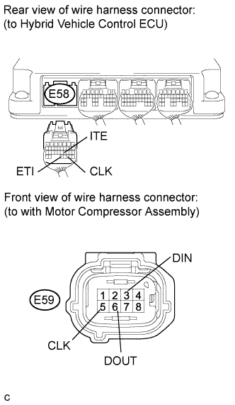
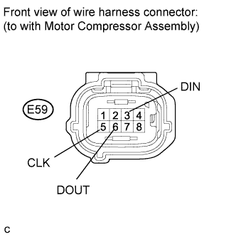
Standard voltage Tester Connection Switch Condition Specified Condition E58-30 (CLK) - Body ground Power switch on (IG) Below 1 V E58-21 (ITE) - Body ground Power switch on (IG) Below 1 V E58-32 (ETI) - Body ground Power switch on (IG) Below 1 V Note
Turning the power switch on (IG) with the hybrid vehicle control ECU connector disconnected causes other DTCs to be stored. Clear the DTCs after performing this inspection.
-
Turn the power switch off.
-
Measure the resistance according to the value(s) in the table below.
Standard resistance (Check for open) Tester Connection Switch Condition Specified Condition E58-30 (CLK) - E59-5 (CLK) Power switch off Below 1 Ω E58-21 (ITE) - E59-3 (DIN) Power switch off Below 1 Ω E58-32 (ETI) - E59-6 (DOUT) Power switch off Below 1 Ω Standard resistance (Check for short) Tester Connection Switch Condition Specified Condition E58-30 (CLK) or E59-5 (CLK) - Body ground and other terminals Power switch off 10 kΩ or higher E58-21 (ITE) or E59-3 (DIN) - Body ground and other terminals Power switch off 10 kΩ or higher E58-32 (ETI) or E59-6 (DOUT) - Body ground and other terminals Power switch off 10 kΩ or higher
NG
REPAIR OR REPLACE HARNESS OR CONNECTOR
OK
-
-
CHECK HYBRID VEHICLE CONTROL ECU
-
Turn the power switch off.
-
Connect the hybrid vehicle control ECU connector.
-
Measure the resistance according to the value(s) in the table below.
Standard resistance Tester Connection Switch Condition Specified Condition E59-6 (DOUT) - Body ground Power switch off 10 kΩ or higher -
Turn the power switch on (IG).
-
Measure the voltage according to the value(s) in the table below.
Standard voltage Tester Connection Switch Condition Specified Condition E59-5 (CLK) - Body ground Power switch on (IG) 10 to 14 V E59-3 (DIN) - Body ground Power switch on (IG) 10 to 14 V E59-6 (DOUT) - Body ground Power switch on (IG) Below 1 V Note
Turning the power switch on (IG) with the with motor compressor assembly connector disconnected causes other DTCs to be stored. Clear the DTCs after performing this inspection.
NG
REPLACE HYBRID VEHICLE CONTROL ECU Click here
OK
-
-
CHECK WITH MOTOR COMPRESSOR ASSEMBLY
-
Turn the power switch off.
-
Connect the with motor compressor assembly connector.
-
Disconnect connector E58 from the hybrid vehicle control ECU.
-
Measure the resistance according to the value(s) in the table below.
Standard resistance Tester Connection Switch Condition Specified Condition E58-30 (CLK) - Body ground Power switch off 10 kΩ or higher E58-21 (ITE) - Body ground Power switch off 10 kΩ or higher -
Turn the power switch on (IG).
-
Measure the voltage according to the value(s) in the table below.
Standard voltage Tester Connection Switch Condition Specified Condition E58-32 (ETI) - Body ground Power switch off 10 to 14 V E58-30 (CLK) - Body ground Power switch off Below 1 V E58-21 (ITE) - Body ground Power switch off Below 1 V Note
Turning the power switch on (IG) with the hybrid vehicle control ECU connector disconnected causes other DTCs to be stored. Clear the DTCs after performing this inspection.
NG
REPLACE WITH MOTOR COMPRESSOR ASSEMBLY Click here
OK 
REPLACE HYBRID VEHICLE CONTROL ECU Click here
-
-
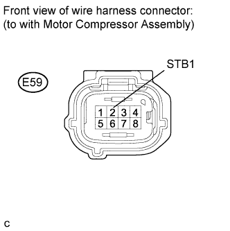
CHECK HARNESS AND CONNECTOR (HYBRID VEHICLE CONTROL ECU - WITH MOTOR COMPRESSOR ASSEMBLY)
-
Turn the power switch off.
-
Disconnect connector E58 from the hybrid vehicle control ECU.
-
Disconnect the with motor compressor assembly connector.
-
Measure the voltage according to the value(s) in the table below.
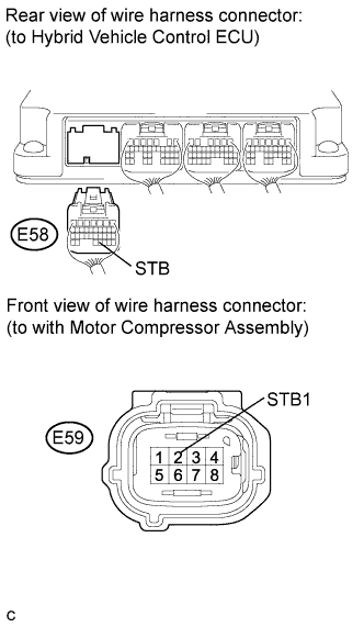
Standard voltage Tester Connection Switch Condition Specified Condition E58-31 (STB) - Body ground Power switch on (IG) Below 1 V Note
Turning the power switch on (IG) with the hybrid vehicle control ECU connector disconnected causes other DTCs to be stored. Clear the DTCs after performing this inspection.
-
Turn the power switch off.
-
Measure the resistance according to the value(s) in the table below.
Standard resistance (Check for open) Tester Connection Switch Condition Specified Condition E58-31 (STB) - E59-2 (STB1) Power switch off Below 1 Ω Standard resistance (Check for short) Tester Connection Switch Condition Specified Condition E58-31 (STB) or E59-2 (STB1) - Body ground and other terminals Power switch off 10 kΩ or higher
NG
REPAIR OR REPLACE HARNESS OR CONNECTOR
OK
-
-
CHECK HYBRID VEHICLE CONTROL ECU
-
Turn the power switch off.
-
Connect the hybrid vehicle control ECU connector.
-
Measure the resistance according to the value(s) in the table below.
Standard resistance Tester Connection Switch Condition Specified Condition E59-2 (STB1) - Body ground Power switch off 10 kΩ or higher -
Turn the power switch on (IG).
-
Measure the voltage according to the value(s) in the table below.
Standard voltage Tester Connection Switch Condition Specified Condition E59-2 (STB1) - Body ground Power switch on (IG) Below 1 V Note
Turning the power switch on (IG) with the with motor compressor assembly connector disconnected causes other DTCs to be stored. Clear the DTCs after performing this inspection.
NG
REPLACE HYBRID VEHICLE CONTROL ECU Click here
OK
-
-
CHECK WITH MOTOR COMPRESSOR ASSEMBLY
-
Turn the power switch off.
-
Connect the with motor compressor assembly connector.
-
Disconnect connector E58 from the hybrid vehicle control ECU.
-
Measure the resistance according to the value(s) in the table below.
Standard resistance Tester Connection Switch Condition Specified Condition E58-31 (STB) - Body ground Power switch off 10 kΩ or higher -
Turn the power switch on (IG).
-
Measure the voltage according to the value(s) in the table below.
Standard voltage Tester Connection Switch Condition Specified Condition E58-31 (STB) - Body ground Power switch on (IG) 10 to 14 V
NG
REPLACE WITH MOTOR COMPRESSOR ASSEMBLY Click here
OK
REPLACE HYBRID VEHICLE CONTROL ECU Click here
-