HYBRID CONTROL SYSTEM, Diagnostic DTC:P0C29-865

| DTC Code | DTC Name |
|---|---|
| P0C29-865 | Auxiliary Transmission Fluid Pump Driver Circuit Performance |
DESCRIPTION
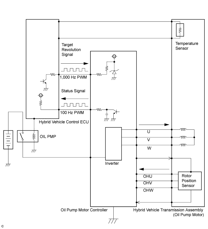
The oil pump motor controller controls the rotation speed of the oil pump motor (three-phase brushless motor) in accordance with rotation speed request signals sent from the hybrid vehicle control ECU. The controller also outputs the oil pump motor status as a signal to the hybrid vehicle control ECU.
| DTC No. | INF Code | DTC Detection Condition | Trouble Area |
|---|---|---|---|
| P0C29 | 865 | The hybrid vehicle control ECU receives signals that indicate an abnormal condition of components (such as the oil pump motor controller or oil pump motor) from the oil pump motor controller. Signals indicating that the oil pump is locked (there is no edge output from the rotor position sensor although a motor operation request is sent) or a malfunction in the oil pump motor controller are received. |
|
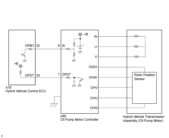
WIRING DIAGRAM
INSPECTION PROCEDURE
PROCEDURE
-
CHECK DTC OUTPUT (HV)
-
Connect the intelligent tester to the DLC3.
-
Turn the power switch on (IG).
-
Select the following menu items: Powertrain / Hybrid Control / Trouble Codes.
-
Check if DTCs are output.
Result Result Proceed to P0C29-865 only is output. A P0C2E-859 is output. B
B 
GO TO DTC CHART Click here
A 
-
-
CHECK FREEZE FRAME DATA (AUXILIARY BATTERY VOLTAGE)
-
Select the following menu items: Powertrain / Hybrid Control / Trouble Codes.
-
Read the freeze frame data (auxiliary battery voltage (+B)) of DTC PP0C29-865.
OK +B is 10 V or more.
NG
CHECK AUXILIARY BATTERY
OK
-
-
CLEAR DTC
-
Select the following menu items: Powertrain / Hybrid Control / Trouble Codes.
-
Read and record the DTCs and freeze frame data.
-
Select the following menu items: Powertrain / Hybrid Control / Trouble Codes.
-
Clear DTCs and freeze frame data.
NEXT
-
-
CHECK DTC OUTPUT (HV)
-
Turn the power switch on (IG), wait 5 seconds or more and check for DTCs.
-
If DTCs are not output after turning the power switch on (IG), wait 5 seconds or more after ST-on and check for DTCs again (set the vehicle to ST-on after turning the power switch on (IG)).
Tech Tips
ST-on is a state that occurs when the READY indicator in the combination meter blinks after the power switch is pressed with the brake pedal depressed.
Result Result Proceed to The DTC is output several seconds (approximately 5 seconds) after the power switch is turned on (IG). (SI signal circuit) A The DTC is output several seconds (approximately 5 seconds) after the ST-on state occurs. (Motor malfunction) B The DTC is not output. C
B 
CHECK CONNECTOR CONNECTION CONDITION (OIL PUMP MOTOR CONTROLLER CONNECTOR) Click here
C
CHECK FOR INTERMITTENT PROBLEMS Click here
A
-
-
CHECK HYBRID VEHICLE CONTROL ECU (CHECK WAVEFORM)
-
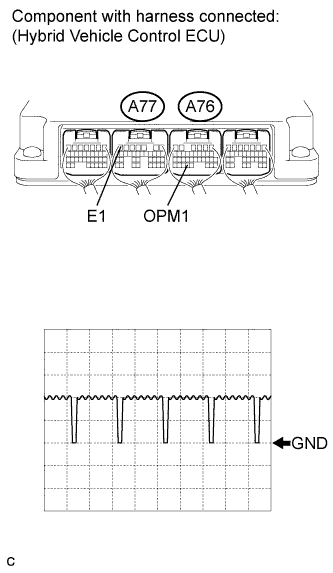
Connect an oscilloscope between the hybrid vehicle control ECU terminals specified in the table below, and measure the waveform.
Item Contents Terminal A76-32 (OPM1) - A77-7 (E1) Equipment Setting 5 V/DIV., 500 μs./DIV. Condition Power switch on (IG) Result Result Proceed to Waveform is flat, and is stuck on the +B side. A Waveform is flat, and is stuck on the GND side. B Normal C
B
CHECK CONNECTOR CONNECTION CONDITION (OIL PUMP MOTOR CONTROLLER) Click here
C
CHECK NOISE CONDITIONS Click here
A
-
-
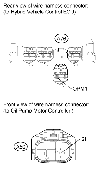
CHECK HARNESS AND CONNECTOR (HYBRID VEHICLE CONTROL ECU - OIL PUMP MOTOR CONTROLLER)
-
Turn the power switch off.
-
Disconnect connector A76 from the hybrid vehicle control ECU.
-
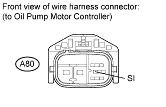
Disconnect connector A80 from the oil pump motor controller.
-
Turn the power switch on (IG).
-
Measure the voltage according to the value(s) in the table below.
Standard voltage Tester Connection Switch Condition Specified Condition A76-32 (OPM1) or A80-6 (SI) - Body ground Power switch on (IG) Below 1 V Note
Turning the power switch on (IG) with the hybrid vehicle control ECU and oil pump motor controller connectors disconnected causes other DTCs to be stored. Clear the DTCs after performing this inspection.
NG
REPAIR OR REPLACE HARNESS OR CONNECTOR
OK
-
-
CHECK HYBRID VEHICLE CONTROL ECU (CHECK +B SHORT)
-
Turn the power switch off.
-
Connect connector A76 to the hybrid vehicle control ECU.
-
Turn the power switch on (IG).
-
Measure the voltage according to the value(s) in the table below.
Standard voltage Tester Connection Switch Condition Specified Condition A80-6 (SI) - Body ground Power switch on (IG) Below 1 V Note
Turning the power switch on (IG) with the oil pump motor controller connector disconnected causes other DTCs to be stored. Clear the DTCs after performing this inspection.
NG
REPLACE HYBRID VEHICLE CONTROL ECU Click here
OK
-
-
CHECK HYBRID VEHICLE CONTROL ECU
-
Turn the power switch on (IG).
-
Measure the frequency according to the value(s) in the table below.
Standard Tester Connection Condition Specified Condition A80-6 (SI) - Body ground Power switch on (IG) Approximately 1 kHz Note
Turning the power switch on (IG) with the oil pump motor controller connector disconnected causes other DTCs to be stored. Clear the DTCs after performing this inspection.
Tech Tips
Perform this inspection with the hybrid vehicle control ECU connectors connected.
NG
REPLACE HYBRID VEHICLE CONTROL ECU Click here
OK 
REPLACE OIL PUMP MOTOR CONTROLLER Click here
-
-
CHECK CONNECTOR CONNECTION CONDITION (OIL PUMP MOTOR CONTROLLER)
Note
Before disconnecting the connectors, confirm that they are properly connected by checking that the locking claws are engaged and that the connectors do not pull out.
-
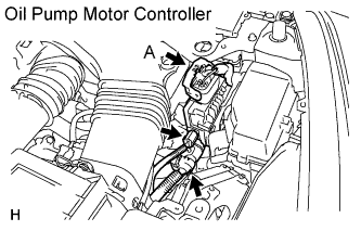
Check the connections of the oil pump motor controller connectors.
OK The connectors are connected securely and there are no contact problems. Tech Tips
For connector A, when connecting it, insert it with the locking lever in the raised position. Rotate the lever downward and make sure that the connector is pulled into its socket. When the locking lever is in its fully closed position, a click will be heard as its locking claws engage. After the click is heard, pull up on the connector to confirm that it is properly connected.
NG
CONNECT SECURELY
OK
-
-
CHECK CONNECTOR CONNECTION CONDITION (HYBRID VEHICLE CONTROL ECU CONNECTOR)
-
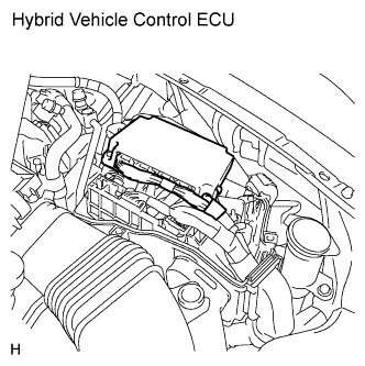
Check the connections of the hybrid vehicle control ECU connectors.
OK The connectors are connected securely and there are no contact problems.
NG
CONNECT SECURELY
OK
-
-
CHECK HARNESS AND CONNECTOR (HYBRID VEHICLE CONTROL ECU - OIL PUMP MOTOR CONTROLLER)
-
Turn the power switch off.
-
Disconnect connector A76 from the hybrid vehicle control ECU.
-
Disconnect connector A80 from the oil pump motor controller.
-
Measure the resistance according to the value(s) in the table below.
Standard resistance (Check for open) Tester Connection Switch Condition Specified Condition A76-32 (OPM1) - A80-6 (SI) Power switch off Below 1 Ω Standard resistance (Check for short) Tester Connection Switch Condition Specified Condition A76-32 (OPM1) - Body ground and other terminals Power switch off 10 kΩ or higher
NG
REPAIR OR REPLACE HARNESS OR CONNECTOR
OK
-
-
CHECK HYBRID VEHICLE CONTROL ECU (CHECK GND SHORT)
-
Connect connector A76 to the hybrid vehicle control ECU.
-
Measure the resistance according to the value(s) in the table below.
Standard resistance Tester Connection Switch Condition Specified Condition A80-6 (SI) - Body ground Power switch off 10 kΩ or higher
NG
REPLACE HYBRID VEHICLE CONTROL ECU Click here
OK
-
-
CHECK HYBRID VEHICLE CONTROL ECU
-
Turn the power switch on (IG).
-
Measure the frequency according to the value(s) in the table below. (Hz)
Standard Tester Connection Switch Condition Specified Condition A80-6 (SI) - Body ground Power switch on (IG) Approximately 1 kHz Note
Turning the power switch on (IG) with the oil pump motor controller connector disconnected causes other DTCs to be stored. Clear the DTCs after performing this inspection.
Tech Tips
Perform this inspection with the hybrid vehicle control ECU connectors connected.
NG
REPLACE HYBRID VEHICLE CONTROL ECU Click here
OK
REPLACE OIL PUMP MOTOR CONTROLLER Click here
-
-
CHECK CONNECTOR CONNECTION CONDITION (OIL PUMP MOTOR CONTROLLER CONNECTOR)
Note
Before disconnecting the connectors, confirm that they are properly connected by checking that the locking claws are engaged and that the connectors do not pull out.
-
Check the connections of the oil pump motor controller connectors.
OK The connectors are connected securely and there are no contact problems. Tech Tips
For connector A, when connecting it, insert it with the locking lever in the raised position. Rotate the lever downward and make sure that the connector is pulled into its socket. When the locking lever is in its fully closed position, a click will be heard as its locking claws engage. After the click is heard, pull up on the connector to confirm that it is properly connected.
NG
CONNECT SECURELY
OK
-
-
CHECK IF PART IS CORRECTLY GROUNDED
-
Measure the resistance according to the value(s) in the table below.
Standard resistance Tester Connection Switch Condition Specified Condition Oil pump motor controller - Body ground Power switch off Below 1 Ω
NG
REPAIR OR REPLACE OIL PUMP MOTOR CONTROLLER
OK
-
-
REPLACE OIL WITH MOTOR PUMP ASSEMBLY
-
Replace the oil with motor pump assembly Click here.
NEXT
-
-
CLEAR DTC
-
Select the following menu items: Powertrain / Hybrid Control / Trouble Codes.
-
Read and record the DTCs and freeze frame data.
-
Select the following menu items: Powertrain / Hybrid Control / Trouble Codes.
-
Clear DTCs and freeze frame data.
NEXT
-
-
CHECK DTC OUTPUT (HV)
-
Connect the intelligent tester to the DLC3.
-
Turn the power switch on (IG), wait 5 seconds or more and check for DTCs.
-
If DTCs are not output after turning the power switch on (IG), wait 5 seconds or more after ST-on and check for DTCs again (set the vehicle to ST-on after turning the power switch on (IG)).
Tech Tips
ST-on is a state that occurs when the READY indicator in the combination meter blinks after the power switch is pressed with the brake pedal depressed.
-
Select the following menu items: Powertrain / Hybrid Control / Trouble Codes.
-
Check if DTCs are output.
Result Result Proceed to P0C29-865 is not output. A P0C29-865 is output. B
B
REPLACE OIL PUMP MOTOR CONTROLLER Click here
A
END
-
-
CHECK NOISE CONDITIONS
-
Check the waveform for an interruption or distortion.
Result Result Proceed to There are no interruptions or distortions in the waveform. A There is an interruption or distortion in the waveform. B
B
CLEAR NOISE CONDITIONS
A
REPLACE OIL PUMP MOTOR CONTROLLER Click here
-