HYBRID CONTROL SYSTEM, Diagnostic DTC:P0AA1-233

| DTC Code | DTC Name |
|---|---|
| P0AA1-233 | Hybrid Battery Positive Contactor Circuit Stuck Closed |
DESCRIPTION
-
Refer to the description for DTC P0AE6-225 Click here.
-
This circuit uses the hybrid vehicle control ECU to monitor the system main relays and stops the system if a malfunction is detected in the relays, because it may be impossible to shut off the high-voltage system if any of the relays becomes stuck.
| DTC No. | INF Code | DTC Detection Condition | Trouble Area |
|---|---|---|---|
| P0AA1 | 233 | SMRB and SMRG on the HV battery positive and negative sides are stuck closed. | HV battery junction block |
WIRING DIAGRAM
Refer to the wiring diagram for DTC P0AE6-225 Click here.
INSPECTION PROCEDURE
CAUTION:
-
Before inspecting the high-voltage system or disconnecting the low voltage connector of the inverter with converter assembly, take safety precautions such as wearing insulated gloves and removing the service plug grip to prevent electrical shocks. After removing the service plug grip, put it in your pocket to prevent other technicians from accidentally reconnecting it while you are working on the high-voltage system.
-
After disconnecting the service plug grip, wait for at least 10 minutes before touching any of the high-voltage connectors or terminals. After waiting for 10 minutes, check the voltage at the terminals in the inspection point in the inverter with converter assembly. The voltage should be 0 V before beginning work.
Tech Tips
-
Waiting for at least 10 minutes is required to discharge the high-voltage capacitor inside the inverter with converter assembly.
-
If P0AA1-233 is stored, the hybrid system cannot be turned on.
PROCEDURE
-
CHECK DTC OUTPUT (HV)
-
Connect the intelligent tester to the DLC3.
-
Turn the power switch on (IG).
-
Select the following menu items: Powertrain / Hybrid Control / Trouble Codes.
-
Check if DTCs are output.
Result Result Proceed to P0AA1-233 only is output. A Any of the following DTCs are also output. B DTC No. Relevant Diagnosis P0A1A-151, 155, 156, 200, 201, 658, 659, 791, 792, 793 Generator Control Module P0A1B-163, 164, 168, 192, 193, 511, 512, 661, 786, 788, 794, 795, 796 Drive Motor "A" Control Module P0A3F-243 Drive Motor "A" Position Sensor Circuit P0A40-500 Drive Motor "A" Position Sensor Circuit Range / Performance P0A41-245 Drive Motor "A" Position Sensor Circuit Low P0A4B-253 Generator Position Sensor Circuit P0A4C-513 Generator Position Sensor Circuit Range / Performance P0A4D-255 Generator Position Sensor Circuit Low P0A78-113, 121, 266, 267, 279, 282, 284, 286, 287, 306, 503, 504, 505, 506, 586 Drive Motor "A" Inverter Performance P0A7A-122, 322, 324, 325, 344, 517, 518 Generator Inverter Performance P0A90-509 Drive Motor "A" Performance P0A92-521 Hybrid Generator Performance P0A94-442 DC / DC Converter Performance P0ADC-226 Hybrid Battery Positive Contactor Control Circuit High P0AE0-228 Hybrid Battery Negative Contactor Control Circuit High P0C76-523 Hybrid Battery System Discharge Time Too Long P3004-132 Power Cable Malfunction P3240-443 DC / DC Converter Control Circuit
B 
GO TO DTC CHART Click here
A 
-
-
CHECK FREEZE FRAME DATA
-
Turn the power switch on (IG).
-
Select the following menu items: Powertrain / Hybrid Control / Trouble Codes.
-
Read the freeze frame data of DTC P0A94-587.
Result Result Proceed to Difference between VH-Voltage after Boosting and VL-Voltage before Boosting is 100 V or less. A Difference between VH-Voltage after Boosting and VL-Voltage before Boosting is more than 100 V. B
(for LHD)
C
(for RHD)
B
REPLACE INVERTER WITH CONVERTER ASSEMBLY Click here
C
REPLACE INVERTER WITH CONVERTER ASSEMBLY Click here
A
-
-
CHECK HV BATTERY JUNCTION BLOCK
CAUTION:
Be sure to wear insulated gloves.
-
Turn the power switch off.
-
Remove the service plug grip. Click here
Note
After removing the service plug grip, do not turn the power switch on (READY) unless instructed by the repair manual because this may cause a malfunction.
-
Disconnect the high-voltage connector of the HV battery junction block.
Tech Tips
For the removal and installation procedures related to inspection of the HV battery junction block, Click here.
-
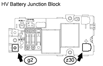
Measure the resistance according to the value(s) in the table below.
Standard resistance Tester Connection Switch Condition Specified Condition g2-1 - z30-1 Power switch off 10 kΩ or higher Tech Tips
If a system main relay is stuck closed, impacts or vibrations during the inspection may cause it to open.
-
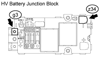
Measure the resistance according to the value(s) in the table below.
Standard resistance Tester Connection Switch Condition Specified Condition g3-1 - z34-1 Power switch off 10 kΩ or higher Tech Tips
If a system main relay is stuck closed, impacts or vibrations during the inspection may cause it to open.
NG
REPLACE HV BATTERY JUNCTION BLOCK Click here
OK 
REPLACE HV BATTERY JUNCTION BLOCK Click here
-