HYBRID CONTROL SYSTEM, Diagnostic DTC:P0A08-264

| DTC Code | DTC Name |
|---|---|
| P0A08-264 | DC / DC Converter Status Circuit |
DESCRIPTION
For a description of the hybrid vehicle converter (DC/DC converter), Click here.
| DTC No. | INF Code | DTC Detection Condition | Trouble Area |
|---|---|---|---|
| P0A08 | 264 | Malfunction in the hybrid vehicle converter |
|
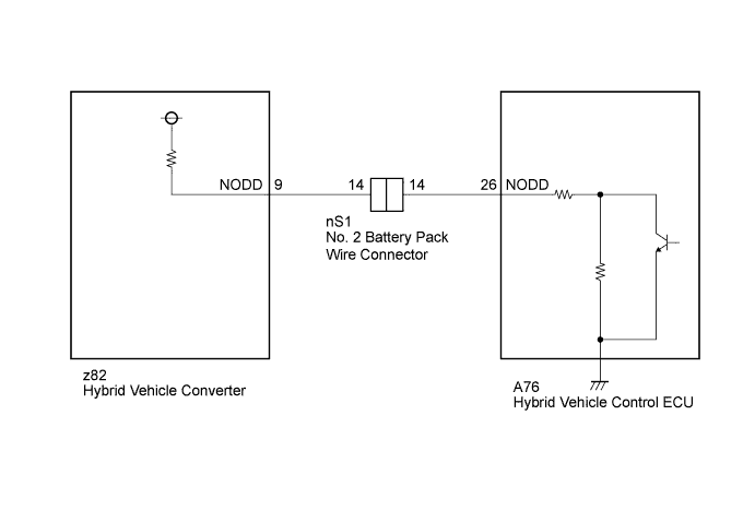
WIRING DIAGRAM
INSPECTION PROCEDURE
CAUTION:
-
Before inspecting the high-voltage system or disconnecting the low voltage connector of the inverter with converter assembly, take safety precautions such as wearing insulated gloves and removing the service plug grip to prevent electrical shocks. After removing the service plug grip, put it in your pocket to prevent other technicians from accidentally reconnecting it while you are working on the high-voltage system.
-
After disconnecting the service plug grip, wait for at least 10 minutes before touching any of the high-voltage connectors or terminals. After waiting for 10 minutes, check the voltage at the terminals in the inspection point in the inverter with converter assembly. The voltage should be 0 V before beginning work.
Tech Tips
Waiting for at least 10 minutes is required to discharge the high-voltage capacitor inside the inverter with converter assembly.
PROCEDURE
-
CHECK DTC OUTPUT (HV)
-
Connect the intelligent tester to the DLC3.
-
Turn the power switch on (IG).
-
Select the following menu items: Powertrain / Hybrid Control / Trouble Codes.
-
Check if DTCs are output.
Result Result Proceed to P0A08-264 only is output. A Any of the following DTCs are also output. B DTC No. Relevant Diagnosis P0A94-127, 547, 548, 549, 550 DC / DC Converter Performance P0ADB-227 Hybrid Battery Positive Contactor Control Circuit Low P0ADC-226 Hybrid Battery Positive Contactor Control Circuit High P0ADF-229 Hybrid Battery Negative Contactor Control Circuit Low P0AE0-228 Hybrid Battery Negative Contactor Control Circuit High P0AE6-225 Hybrid Battery Precharge Contactor Control Circuit Low P3004-131, 803 Power Cable Malfunction
B 
GO TO DTC CHART Click here
A 
-
-
CHECK CONNECTOR CONNECTION CONDITION (HYBRID VEHICLE CONTROL ECU CONNECTOR)
-
Check the connections of the hybrid vehicle control ECU connectors.
OK The connectors are connected securely and there are no contact problems.
NG
CONNECT SECURELY
OK
-
-
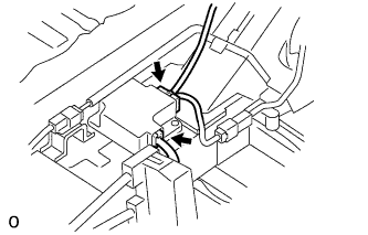
CHECK FRAME WIRE (ENGINE ROOM NO. 1 JUNCTION BLOCK SIDE)
CAUTION:
Be sure to wear insulated gloves.
-
Turn the power switch off.
-
Remove the service plug grip. Click here
Note
After removing the service plug grip, do not turn the power switch on (READY) unless instructed by the repair manual because this may cause a malfunction.
-
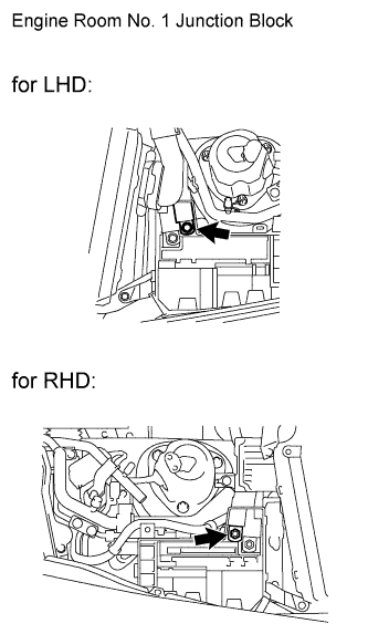
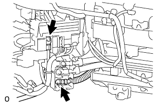
Check the connection of the frame wire terminal (engine room No. 1 junction block side).
OK The terminal is connected securely and there is no contact problem. -
Check for arc marks on the frame wire terminals (engine room No. 1 junction block side and vehicle wire harness side).
Result Result Proceed to The terminals are connected securely and there are no contact problems. There are no arc marks. A The terminals are not connected securely and there is a contact problem. There are arc marks. B The terminals are not connected securely and there is a contact problem. There are no arc marks. C The terminals are connected securely and there are no contact problems. There are arc marks. B
B
REPAIR OR REPLACE MALFUNCTIONING PARTS, COMPONENT AND AREA
C
CONNECT SECURELY
A
-
-
CHECK FUSES
-
Measure the resistance of the headlight system, A/C blower system, defogger system, stop light system and power window system fuses.
OK Below 1 Ω Tech Tips
If any of the fuses is broken, replace the fuse and repair the shorted circuit.
NG
REPAIR OR REPLACE SHORTED CIRCUIT AND REPLACE BROKEN FUSE
OK
-
-
CHECK CONNECTOR CONNECTION CONDITION (NO. 2 BATTERY PACK WIRE CONNECTOR)
-
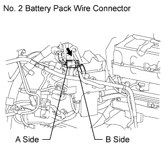
Check the connection of the No. 2 battery pack wire connector.
OK The connector is connected securely and there are no contact problems. Tech Tips
For the removal and installation procedures related to inspection of the connection of the No. 2 battery pack wire connector, Click here.
NG
CONNECT SECURELY
OK
-
-
CHECK HARNESS AND CONNECTOR (RESISTANCE VALUE OF NODD INSIDE HYBRID VEHICLE CONTROL ECU)
-
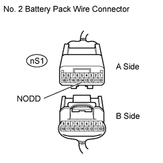
Disconnect the No. 2 battery pack wire connector.
-
Measure the resistance according to the value(s) in the table below.
Standard resistance Tester Connection Switch Condition Specified Condition nS1-14 (NODD) - Body ground Power switch off 120 to 140 kΩ
NG 
CHECK HARNESS AND CONNECTOR (HYBRID VEHICLE CONTROL ECU - NO. 2 BATTERY PACK WIRE CONNECTOR) Click here
OK
-
-
CHECK FRAME WIRE (NO. 2 FUSIBLE LINK BLOCK ASSEMBLY SIDE)
CAUTION:
Be sure to wear insulated gloves.
-
Check that the service plug grip is not installed.
-
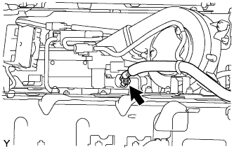
Check the connection of the frame wire terminal (No. 2 fusible link block assembly side).
OK The terminal is connected securely and there is no contact problem. -
Check for arc marks on the frame wire terminals (No. 2 fusible link block assembly side and vehicle wire harness side).
Result Result Proceed to The terminals are connected securely and there are no contact problems. There are no arc marks. A The terminals are not connected securely and there is a contact problem. There are arc marks. B The terminals are not connected securely and there is a contact problem. There are no arc marks. C The terminals are connected securely and there are no contact problems. There are arc marks. B
B
REPAIR OR REPLACE MALFUNCTIONING PARTS, COMPONENT AND AREA
C
CONNECT SECURELY
A
-
-
CHECK HV CONVERTER (AMD TERMINAL CONNECTION CONDITION)
CAUTION:
Be sure to wear insulated gloves.
-
Check that the service plug grip is not installed.
-
Check the connection of the AMD terminal (hybrid vehicle converter side).
OK The terminal is connected securely and there is no contact problem. -
Check for arc marks on the AMD terminals (hybrid vehicle converter side and vehicle wire harness side).
Result Result Proceed to The terminals are connected securely and there are no contact problems. There are no arc marks. A The terminals are not connected securely and there is a contact problem. There are arc marks. B The terminals are not connected securely and there is a contact problem. There are no arc marks. C The terminals are connected securely and there are no contact problems. There are arc marks. B
B
REPAIR OR REPLACE MALFUNCTIONING PARTS, COMPONENT AND AREA
C
CONNECT SECURELY
A
-
-
CHECK HV CONVERTER (INSTALLATION CONDITION)
CAUTION:
Be sure to wear insulated gloves.
-
Check that the service plug grip is not installed.
-
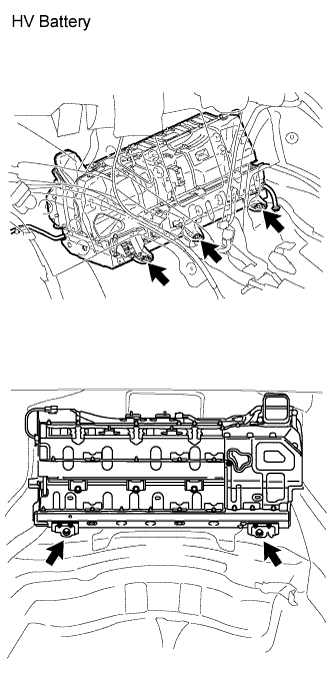
Check that the HV battery assembly installation bolts are tightened to the specified torque. Check that the HV battery assembly installation bolts are connected securely and that there are no contact problems.
Torque Bolts 20 N*m (204 kgf*cm, 15 ft.*lbf) -
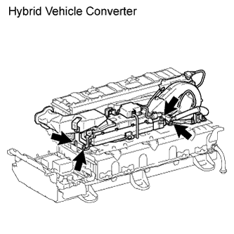
Check that the hybrid vehicle converter installation nuts are tightened to the specified torque. Check that the hybrid vehicle converter installation nuts are connected securely and that there are no contact problems.
Torque Nuts 7.5 N*m (77 kgf*cm, 66 in.*lbf) -
Check for arc marks at each nut and bolt.
Result Result Proceed to There are no loose connections or contact problems. There are no arc marks. A There is a loose connection or contact problem. There are arc marks. B There is a loose connection or contact problem. There are no arc marks. C There are no loose connections or contact problems. There are arc marks. B Tech Tips
Because the hybrid vehicle converter is grounded to the body, DTC P0A08-264 may be set if there are any contact or connection problems.
B
REPAIR OR REPLACE MALFUNCTIONING PARTS, COMPONENT AND AREA
C
CONNECT SECURELY
A
-
-
CHECK CONNECTOR CONNECTION CONDITION (HV BATTERY JUNCTION BLOCK CONNECTOR)
CAUTION:
Be sure to wear insulated gloves.
-
Check that the service plug grip is not installed.
-
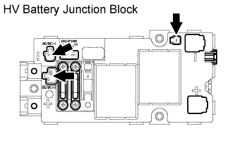
Check the connections of the high-voltage connectors for the hybrid vehicle converter that are connected to the HV battery junction block.
Tech Tips
For the removal and installation procedures related to inspection of the connections of the high-voltage connectors for the hybrid vehicle converter, Click here.
OK The connectors are connected securely and there are no contact problems.
NG
CONNECT SECURELY
OK
-
-
CHECK HV BATTERY JUNCTION BLOCK (ELECTRIC BATTERY FUSE)
CAUTION:
Be sure to wear insulated gloves.
-
Check that the service plug grip is not installed.
-
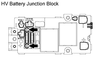
Check if there is an open circuit in the electric battery fuse that is installed in the HV battery junction block.
OK There is no open circuit in the fuse. -
Check that the bolts for the electric battery fuse are tightened to the specified torque.
Specified Condition T= 4.5 N*m {46 kgf*cm, 40 in.*lbf} Note
Be sure to use a torque wrench to check the tightening torque.
NG
REPLACE ELECTRIC BATTERY FUSE Click here
OK
-
-
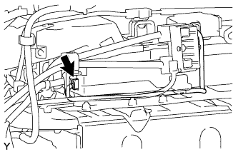
CHECK CONNECTOR CONNECTION CONDITION (HYBRID VEHICLE CONVERTER CONNECTOR)
CAUTION:
Be sure to wear insulated gloves.
-
Check that the service plug grip is not installed.
Note
After removing the service plug grip, do not turn the power switch on (READY) unless instructed by the repair manual because this may cause a malfunction.
-
Check the connection of the low voltage connector of the hybrid vehicle converter.
OK The connector is connected securely and there are no contact problems. Tech Tips
For the removal and installation procedures related to inspection of the connection of the low voltage connector of the hybrid vehicle converter, Click here.
NG
CONNECT SECURELY
OK
-
-
CHECK HARNESS AND CONNECTOR (NO. 2 BATTERY PACK WIRE CONNECTOR - HYBRID VEHICLE CONVERTER)
CAUTION:
Be sure to wear insulated gloves.
-
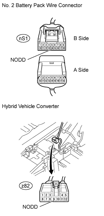
Check that the service plug grip is not installed.
-
Disconnect the low voltage connector from the hybrid vehicle converter.
Tech Tips
For the removal and installation procedures related to the low voltage connector of the hybrid vehicle converter, Click here.
-
Measure the resistance according to the value(s) in the table below.
Standard resistance Tester Connection Switch Condition Specified Condition nS1-14 (NODD) - z82-9 (NODD) Power switch off Below 1 Ω
NG
REPAIR OR REPLACE HARNESS OR CONNECTOR
OK
-
-
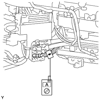
INSPECT HV CONVERTER
-
Connect all the disconnected connectors.
-
Install the service plug grip.
-
Measure the current output from the hybrid vehicle converter with the headlight position switch and blower motor switch in the HI position, and the rear window defogger turned on. (*1)
-
Measure the auxiliary battery voltage according to the previous conditions (*1).
Result Item Condition Specified Condition Current flowing from the hybrid vehicle converter The headlight position switch and blower motor switch are in the HI position, and the rear window defogger is turned on. 60 to 140 A Auxiliary battery voltage The headlight position switch and blower motor switch are in the HI position, and the rear window defogger is turned on. 13 to 15 V
NG
REPLACE HV CONVERTER Click here
OK
-
-
CHECK FOR INTERMITTENT PROBLEMS
-
Check for intermittent problems Click here.
NG
REPAIR OR REPLACE MALFUNCTIONING PARTS, COMPONENT AND AREA
OK 
REPLACE HV CONVERTER Click here
-
-
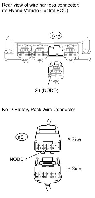
CHECK HARNESS AND CONNECTOR (HYBRID VEHICLE CONTROL ECU - NO. 2 BATTERY PACK WIRE CONNECTOR)
-
Disconnect connector A76 from the hybrid vehicle control ECU.
-
Turn the power switch on (IG).
-
Measure the voltage according to the value(s) in the table below.
Tech Tips
Turning the power switch on (IG) with the service plug grip removed causes an interlock switch system DTC (P0A0D-350) to be set.
Standard voltage Tester Connection Switch Condition Specified Condition A76-26 (NODD) - Body ground Power switch on (IG) Below 1 V Note
Turning the power switch on (IG) with the hybrid vehicle control ECU connector disconnected causes other DTCs to be stored. Clear the DTCs after performing this inspection.
-
Turn the power switch off.
-
Measure the resistance according to the value(s) in the table below.
Standard resistance (Check for open) Tester Connection Switch Condition Specified Condition A76-26 (NODD) - nS1-14 (NODD) Power switch off Below 1 Ω Standard resistance (Check for short) Tester Connection Switch Condition Specified Condition A76-26 (NODD) or nS1-14 (NODD) - Body ground and other terminals Power switch off 10 kΩ or higher
NG
REPAIR OR REPLACE HARNESS OR CONNECTOR
OK
REPLACE HYBRID VEHICLE CONTROL ECU Click here
-