HYBRID CONTROL SYSTEM, Diagnostic DTC:P0A2C-247, P0A2D-249

| DTC Code | DTC Name |
|---|---|
| P0A2C-247 | Drive Motor "A" Temperature Sensor Circuit Low |
| P0A2D-249 | Drive Motor "A" Temperature Sensor Circuit High |
DESCRIPTION
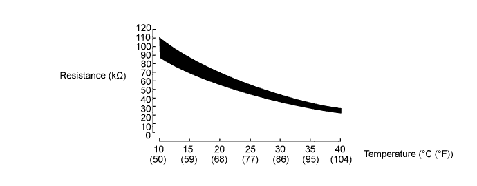
The resistance of the thermistor built into the motor temperature sensor changes in accordance with changes in MG2 temperature. The lower the MG2 temperature, the higher the thermistor resistance. Conversely, the higher the temperature, the lower the resistance.
Tech Tips
The term "drive motor A" indicates MG2.
| DTC No. | INF Code | DTC Detection Condition | Trouble Area |
|---|---|---|---|
| P0A2C | 247 | Short to GND in the motor temperature sensor circuit |
|
| P0A2D | 249 | Open or short to +B in the motor temperature sensor circuit |
Tech Tips
After confirming that DTC P0A2C-247 or P0A2D-249 is output, use the intelligent tester to check "Motor Temp No1" in the HV ECU data list.
| Displayed Temperature | Malfunction |
|---|---|
| -50°C (58°F) | Open circuit or short to +B |
| 205°C (401°F) | Short to GND |
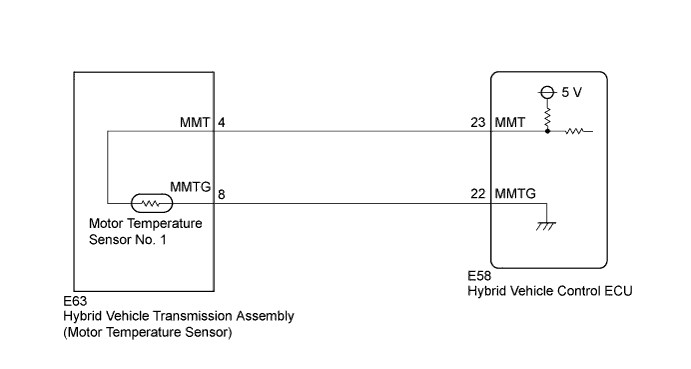
WIRING DIAGRAM
INSPECTION PROCEDURE
PROCEDURE
-
CHECK CONNECTOR CONNECTION CONDITION (HYBRID VEHICLE CONTROL ECU CONNECTOR)
-
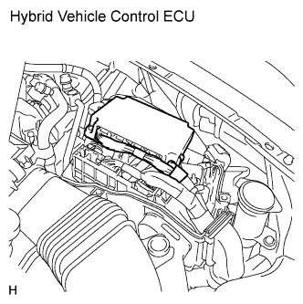
Check the connections of the hybrid vehicle control ECU connectors.
OK The connectors are connected securely and there are no contact problems.
NG 
CONNECT SECURELY
OK 
-
-
READ VALUE USING INTELLIGENT TESTER (MOTOR1 TEMP)
-
Connect the intelligent tester to the DLC3.
-
Turn the power switch on (IG).
-
Select the following menu items: Powertrain / Hybrid Control / Data List / Motor Temp No1.
-
Read the data list.
Result Result Proceed to -50°C (-58°F) A 205°C (401°F) B Same as actual temperature C
B 
READ VALUE USING INTELLIGENT TESTER (CHECK FOR SHORT) Click here
C
CHECK FOR INTERMITTENT PROBLEMS Click here
A
-
-
READ VALUE USING INTELLIGENT TESTER (CHECK FOR OPEN)
-
Turn the power switch off.
-
Disconnect the motor temperature sensor connector.
-
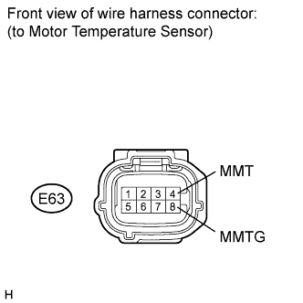
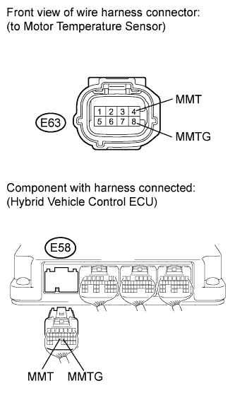
Connect terminals 4 (MMT) and 8 (MMTG) of the vehicle side connector of the motor temperature sensor.
-
Turn the power switch on (IG).
-
Select the following menu items: Powertrain / Hybrid Control / Data List / Motor Temp No1.
-
Read the data list.
OK Tester Display Condition Specified Condition Motor Temp No1 Terminals MMT and MMTG connected.
Power switch on (IG)
205°C (401°F)
NG
CHECK HARNESS AND CONNECTOR (HYBRID VEHICLE CONTROL ECU - MOTOR TEMPERATURE SENSOR) Click here
OK 
REPLACE HYBRID VEHICLE TRANSMISSION ASSEMBLY Click here
-
-
CHECK HARNESS AND CONNECTOR (HYBRID VEHICLE CONTROL ECU - MOTOR TEMPERATURE SENSOR)
-
Turn the power switch off.
-
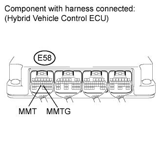
Connect terminals 23 (MMT) and 22 (MMTG) of connector E58 of the hybrid vehicle control ECU.
-
Turn the power switch on (IG).
-
Select the following menu items: Powertrain / Hybrid Control / Data List / Motor Temp No1.
-
Read the data list.
OK Tester Display Condition Specified Condition Motor Temp No1 Terminals MMT and MMTG connected.
Power switch on (IG)
205°C (401°F)
NG
REPAIR OR REPLACE HARNESS OR CONNECTOR
OK
REPLACE HYBRID VEHICLE CONTROL ECU Click here
-
-
READ VALUE USING INTELLIGENT TESTER (CHECK FOR SHORT)
-
Turn the power switch off.
-
Disconnect the motor temperature sensor connector.
-
Turn the power switch on (IG).
-
Select the following menu items: Powertrain / Hybrid Control / Data List / Motor Temp No1.
-
Read the data list.
OK Tester Display Switch Condition Specified Condition Motor Temp No1 Power switch on (IG) -50°C (-58°F)
NG
CHECK HARNESS AND CONNECTOR (HYBRID VEHICLE CONTROL ECU - MOTOR TEMPERATURE SENSOR) Click here
OK
REPLACE HYBRID VEHICLE TRANSMISSION ASSEMBLY Click here
-
-
CHECK HARNESS AND CONNECTOR (HYBRID VEHICLE CONTROL ECU - MOTOR TEMPERATURE SENSOR)
-
Turn the power switch off.
-
Disconnect connector E58 from the hybrid vehicle control ECU.
-
Measure the resistance according to the value(s) in the table below.
Standard resistance (Check for open) Tester Connection Switch Condition Specified Condition E58-23 (MMT) - E63-4 (MMT) Power switch off Below 1 Ω E58-22 (MMTG) - E63-8 (MMTG) Power switch off Below 1 Ω Standard resistance (Check for short) Tester Connection Switch Condition Specified Condition E58-23 (MMT) or E63-4 (MMT) - Body ground and other terminals Power switch off 10 kΩ or higher E58-22 (MMTG) or E63-8 (MMTG) - Body ground and other terminals Power switch off 10 kΩ or higher
NG
REPAIR OR REPLACE HARNESS OR CONNECTOR
OK
REPLACE HYBRID VEHICLE CONTROL ECU Click here
-