HYBRID CONTROL SYSTEM, Diagnostic DTC:P0A01-725, P0A01-726

| DTC Code | DTC Name |
|---|---|
| P0A01-725 | Motor Electronics Coolant Temperature Sensor Circuit Range / Performance |
| P0A01-726 | Motor Electronics Coolant Temperature Sensor Circuit Range / Performance |
DESCRIPTION
Refer to the description for DTC P0A02-719 Click here and DTC P0A93-346 Click here.
| DTC No. | INF Code | DTC Detection Condition | Trouble Area |
|---|---|---|---|
| P0A01 | 725 | Unusual sudden change in HV coolant temperature sensor output occurs and the offset continues, or unusual sudden change in HV coolant temperature sensor output occurs repeatedly. |
|
| P0A01 | 726 | HV coolant temperature sensor output deviation (Temperature calculated by ECU and actual temperature are different for 10 seconds or more.) |
INSPECTION PROCEDURE
PROCEDURE
-
CHECK DTC OUTPUT (HV)
-
Connect the intelligent tester to the DLC3.
-
Turn the power switch on (IG).
-
Select the following menu items: Powertrain / Hybrid Control / Trouble Codes.
-
Check if DTCs are output.
Result Result Proceed to P0A01-725 or P0A01-726 only is output. A P0A93-346 is also output. B
B 
GO TO DTC CHART Click here
A 
-
-
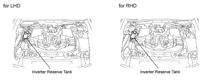
CHECK QUANTITY OF HV COOLANT
-
Check the coolant level in the inverter reserve tank.
-
Check for coolant leaks.
Result Result Proceed to Coolant leaks are not evident. A sufficient amount of coolant remains in the inverter reserve tank. A Coolant leaks are not evident. No coolant remains in the inverter reserve tank. B Coolant leaks are evident. C Tech Tips
After repairing the coolant leaks and adding coolant, perform the "Activate the Water Pump" active test (HV ECU active test item) and the "Control the Electric Cooling Fan" active test (Engine ECU active test item) and make sure that there are no malfunctions.
B
ADD HV COOLANT
C
CHECK FOR COOLANT LEAKS AND ADD COOLANT
A
-
-
CHECK COOLANT HOSE
-
Check if the hoses of the cooling system are kinked or clogged.
NG
CORRECT THE PROBLEM
OK
-
-
PERFORM ACTIVE TEST USING INTELLIGENT TESTER (WATER PUMP)
-
Connect the intelligent tester to the DLC3.
-
Turn the power switch on (IG).
-
Select the following menu items: Powertrain / Hybrid Control / Active Test / Activate the Water Pump.
-
Perform the "Activate the Water Pump" active test for at least 1 minute.
-
Check that there are ripples in the coolant in the inverter reserve tank.
OK There are ripples in the coolant in the inverter reserve tank as long as the active test is being performed. Note
In addition to the active test, the water pump with motor and bracket assembly will also operate with the power switch on (READY). However, the water pump with motor and bracket assembly will operate at low speed for 20 seconds after the power switch is turned on (READY).
Tech Tips
The water pump with motor and bracket assembly will also operate in inspection mode.
NG 
PERFORM ACTIVE TEST USING INTELLIGENT TESTER (WATER PUMP) Click here
OK
-
-
PERFORM ACTIVE TEST USING INTELLIGENT TESTER (COOLING FAN)
-
Select the following menu items: Powertrain / Engine and ECT / Active Test / Control the Electric Cooling Fan.
-
Perform the "Control the Electric Cooling Fan" active test.
OK The cooling fan rotates.
NG
CHECK COOLING FAN SYSTEM Click here
OK
-
-
CHECK CONNECTOR CONNECTION CONDITION (INVERTER WITH CONVERTER ASSEMBLY CONNECTOR)
Note
Before disconnecting the connector, confirm that it is properly connected by checking that the locking claws are engaged and that the connector cannot be pulled out.
-
Check the connection of the low voltage connector of the inverter with converter assembly.
OK The connector is connected securely and there are no contact problems. Tech Tips
When connecting the connector, insert it with the locking lever in the raised position. Rotate the lever downward and make sure that the connector is pulled into its socket. When the locking lever is in its fully closed position, a click will be heard as its locking claws engage. After the click is heard, pull up on the connector to confirm that it is properly connected.
NG
CONNECT SECURELY
OK
-
-
INSPECT COOLING SYSTEM (FOR CLOGGING)
-
Drain the inverter coolant Click here.
Note
Do not reuse the drained coolant because it may contain foreign objects.
Tech Tips
Drain the inverter coolant with the inverter reserve tank cap installed.
-
Install the inverter reserve tank cap.
-
Remove the drain plug.
-
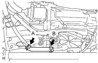
Disconnect end A of the No. 3 inverter cooling hose.
Note
-
Applied air pressure should be 59 kPa (0.6 kgf/cm2, 8.6 psi) or less.
-
Be careful when disconnecting the hose. Coolant may spill out of the hose.
-
-
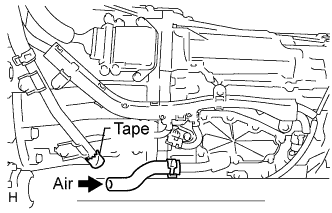
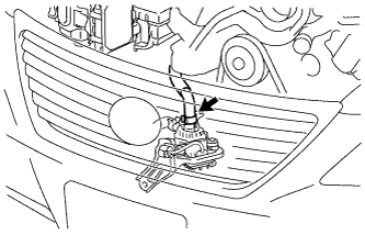
Cover the pipe shown in the illustration with packing tape.
-
Using an air gun, apply air to the disconnected end of the hose to check for clogging in the coolant path.
Note
Be careful when applying air. Applying excessive air may cause coolant to overflow from the inverter reserve tank cap.
OK Coolant and air come out from the drain. -
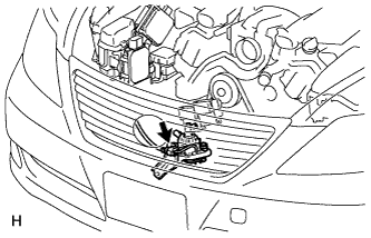
Connect end A of the No. 3 inverter cooling hose and disconnect end B.
-
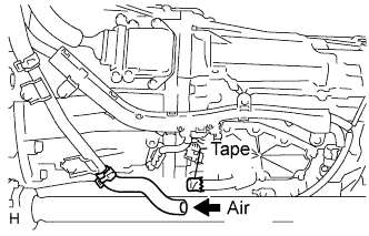
Cover the pipe shown in the illustration with packing tape.
-
Using an air gun, apply air to the disconnected end of the hose to check for clogging in the coolant path.
Note
-
Applied air pressure should be 59 kPa (0.6 kgf/cm2, 8.6 psi) or less.
-
Be careful when applying air. Applying excessive air may cause coolant to overflow from the inverter reserve tank cap.
OK Coolant and air come out from the drain. Result Result Proceed to OK (for LHD) A OK (for RHD) B NG C -
-
After this inspection, check for coolant leaks from the hose with the power switch on (READY).
Note
If leaks are found, replace the No. 3 inverter cooling hose and clamps.
B
REPLACE INVERTER WITH CONVERTER ASSEMBLY Click here
C
REPLACE MALFUNCTIONING PARTS
A 
REPLACE INVERTER WITH CONVERTER ASSEMBLY Click here
-
-
PERFORM ACTIVE TEST USING INTELLIGENT TESTER (WATER PUMP)
-
Connect the intelligent tester to the DLC3.
-
Compress the inlet hose for the water pump with motor and bracket assembly several times.
-
Turn the power switch on (IG) again.
-
Select the following menu items: Powertrain / Hybrid Control / Active Test / Activate the Water Pump.
-
Perform the "Activate the Water Pump" active test for at least 1 minute.
-
Check that there are ripples in the coolant in the inverter reserve tank.
OK There are ripples in the coolant in the inverter reserve tank as long as the active test is being performed. Note
In addition to the active test, the water pump with motor and bracket assembly will also operate with the power switch on (READY). However, the water pump with motor and bracket assembly will operate at low speed for 20 seconds after the power switch is turned on (READY).
Tech Tips
The water pump with motor and bracket assembly will also operate in inspection mode.
NG
CHECK FUSE (INV W/P) Click here
OK
ADD HV COOLANT
-
-
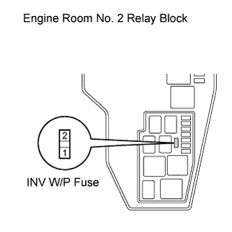
CHECK FUSE (INV W/P)
-
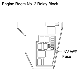
Check if there is an open circuit in the fuse (INV W/P) in the engine room No. 2 relay block.
OK There is no open circuit in the fuse (INV W/P). Tech Tips
If the result is NG, replace the fuse (INV W/P) with a new one.
NG
CHECK CONNECTOR CONNECTION CONDITION (WATER PUMP WITH MOTOR AND BRACKET ASSEMBLY CONNECTOR) Click here
OK
-
-
CHECK CONNECTOR CONNECTION CONDITION (WATER PUMP WITH MOTOR AND BRACKET ASSEMBLY CONNECTOR)
-
Check the connection of the water pump with motor and bracket assembly connector.
OK The connector is connected securely and there are no contact problems.
NG
CONNECT SECURELY
OK
-
-
CHECK CONNECTOR CONNECTION CONDITION (HYBRID VEHICLE CONTROL ECU CONNECTOR)
-
Check the connections of the hybrid vehicle control ECU connectors.
OK The connectors are connected securely and there are no contact problems.
NG
CONNECT SECURELY
OK
-
-
CHECK HARNESS AND CONNECTOR (WATER PUMP WITH MOTOR AND BRACKET ASSEMBLY)
-
Disconnect connector A78 from the hybrid vehicle control ECU.
-
Remove the fuse (INV W/P) from the engine room No. 2 relay block.
-
Disconnect the water pump with motor and bracket assembly connector.
-
Measure the resistance according to the value(s) in the table below.
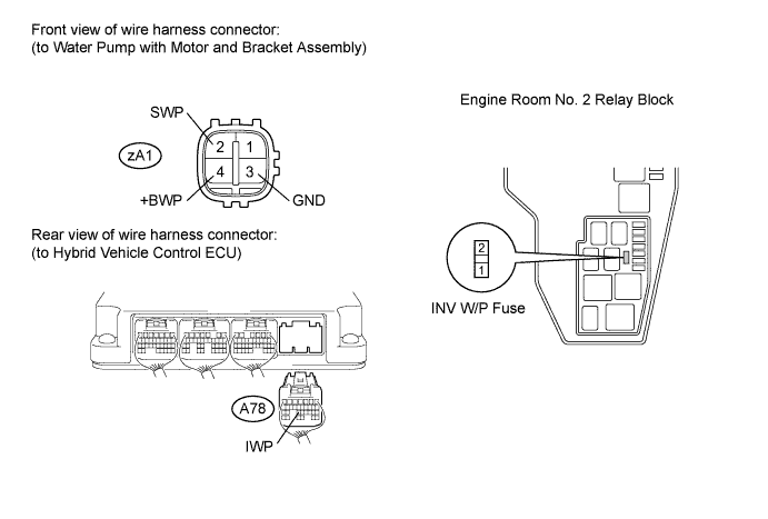
Standard resistance (Check for open) Tester Connection Switch Condition Specified Condition A78-23 (IWP) - zA1-2 (SWP) Power switch off Below 1 Ω zA1-3 (GND) - Body ground Power switch off Below 1 Ω Engine Room No. 2 Relay Block INV W/P Fuse Terminal 2 - zA1-4 (+BWP) Power switch off Below 1 Ω Standard resistance (Check for short) Tester Connection Switch Condition Specified Condition A78-23 (IWP) or zA1-2 (SWP) - Body ground and other terminals Power switch off 10 kΩ or higher Engine Room No. 2 Relay Block INV W/P Fuse Terminal 2 or zA1-4 (+BWP) - Body ground and other terminals Power switch off 10 kΩ or higher
NG
REPAIR OR REPLACE HARNESS OR CONNECTOR
OK
-
-
CHECK WATER PUMP WITH MOTOR AND BRACKET ASSEMBLY
-
Apply 12 V to terminal 2 of the INV W/P fuse holder of the engine room No. 2 relay block and check that the water pump operates.
OK The water pump operates.
NG
REPLACE WATER PUMP WITH MOTOR AND BRACKET ASSEMBLY Click here
OK
REPLACE HYBRID VEHICLE CONTROL ECU Click here
-
-
CHECK CONNECTOR CONNECTION CONDITION (WATER PUMP WITH MOTOR AND BRACKET ASSEMBLY CONNECTOR)
-
Check the connection of the water pump with motor and bracket assembly connector.
OK The connector is connected securely and there are no contact problems.
NG
CONNECT SECURELY
OK
-
-
CHECK CONNECTOR CONNECTION CONDITION (HYBRID VEHICLE CONTROL ECU CONNECTOR)
-
Check the connections of the hybrid vehicle control ECU connectors.
OK The connectors are connected securely and there are no contact problems.
NG
CONNECT SECURELY
OK
-
-
CHECK HARNESS AND CONNECTOR (WATER PUMP WITH MOTOR AND BRACKET ASSEMBLY)
-
Disconnect connector A78 from the hybrid vehicle control ECU.
-
Remove the fuse (INV W/P) from the engine room No. 2 relay block.
-
Disconnect the water pump with motor and bracket assembly connector.
-
Measure the resistance according to the value(s) in the table below.
Standard resistance (Check for open) Tester Connection Switch Condition Specified Condition A78-23 (IWP) - zA1-2 (SWP) Power switch off Below 1 Ω zA1-3 (GND) - Body ground Power switch off Below 1 Ω Engine room No. 2 relay block INV W/P fuse terminal 2 - zA1-4 (+BWP) Power switch off Below 1 Ω Standard resistance (Check for short) Tester Connection Switch Condition Specified Condition A78-23 (IWP) or zA1-2 (SWP) - Body ground and other terminals Power switch off 10 kΩ or higher Engine room No. 2 relay block INV W/P fuse terminal 2 or zA1-4 (+BWP) - Body ground and other terminals Power switch off 10 kΩ or higher
NG
REPAIR OR REPLACE HARNESS OR CONNECTOR
OK
-
-
CHECK WATER PUMP WITH MOTOR AND BRACKET ASSEMBLY
-
Apply 12 V to terminal 2 of the INV W/P fuse holder of the engine room No. 2 relay block and check that the water pump operates.
OK The water pump operates.
NG
REPLACE WATER PUMP WITH MOTOR AND BRACKET ASSEMBLY Click here
OK
REPLACE HYBRID VEHICLE CONTROL ECU Click here
-