HYBRID CONTROL SYSTEM, Diagnostic DTC:P0617-142

| DTC Code | DTC Name |
|---|---|
| P0617-142 | Starter Relay Circuit High |
DESCRIPTION
| DTC No. | INF Code | DTC Detection Condition | Trouble Area |
|---|---|---|---|
| P0617 | 142 | An ST signal from the hybrid vehicle control ECU is present when the power switch is off. |
|
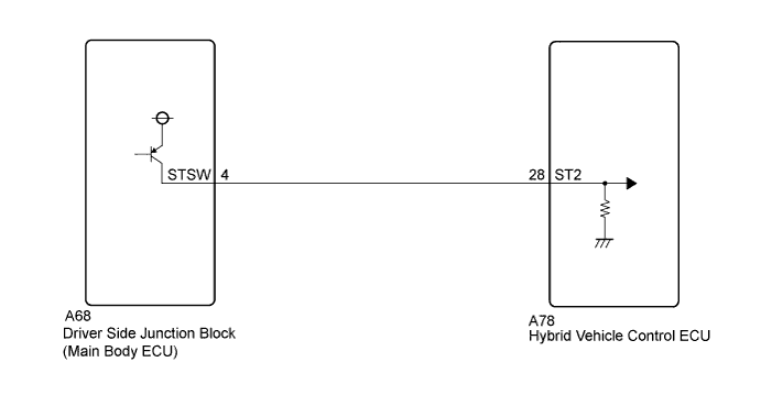
WIRING DIAGRAM
INSPECTION PROCEDURE
PROCEDURE
-
CHECK CONNECTOR CONNECTION CONDITION (HYBRID VEHICLE CONTROL ECU CONNECTOR)
-
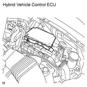
Check the connections of the hybrid vehicle control ECU connectors.
OK The connectors are connected securely and there are no contact problems.
NG 
CONNECT SECURELY
OK 
-
-
CHECK CONNECTOR CONNECTION CONDITION (MAIN BODY ECU CONNECTOR)
-
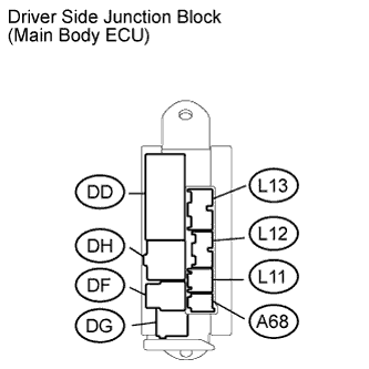
Check the connections of the main body ECU connectors.
OK The connectors are connected securely and there are no contact problems.
NG
CONNECT SECURELY
OK
-
-
CHECK HARNESS AND CONNECTOR (ST2 TERMINAL VOLTAGE)
-
Turn the power switch off.
-
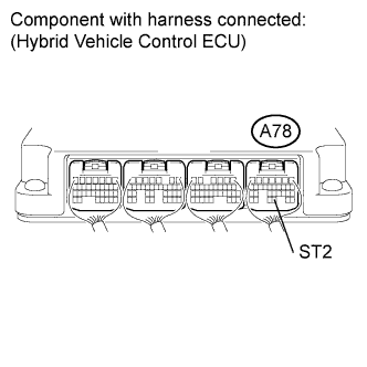
Measure the voltage according to the value(s) in the table below.
Standard voltage Tester Connection Switch Condition Specified Condition A78-28 (ST2) - Body ground Power switch off Below 1 V
NG 
CHECK HARNESS AND CONNECTOR (HYBRID VEHICLE CONTROL ECU - MAIN BODY ECU) Click here
OK 
REPLACE HYBRID VEHICLE CONTROL ECU Click here
-
-
CHECK HARNESS AND CONNECTOR (HYBRID VEHICLE CONTROL ECU - MAIN BODY ECU)
-
Disconnect connector A68 from the driver side junction block (main body ECU).
-
Measure the voltage according to the value(s) in the table below.
Standard voltage Tester Connection Switch Condition Specified Condition A78-28 (ST2) - Body ground Power switch off Below 1 V
NG
REPAIR OR REPLACE HARNESS OR CONNECTOR
OK
REPLACE DRIVER SIDE JUNCTION BLOCK
-