HYBRID CONTROL SYSTEM, Diagnostic DTC:P0560-117

| DTC Code | DTC Name |
|---|---|
| P0560-117 | System Voltage |
DESCRIPTION
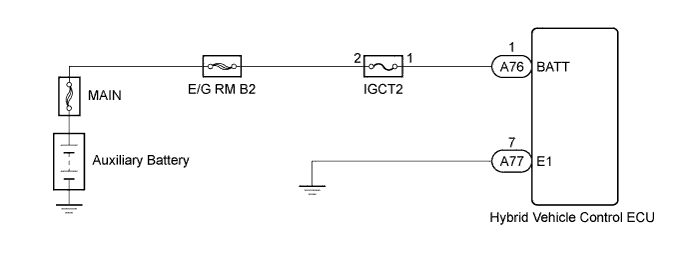
Battery power is constantly supplied to the BATT terminal of the hybrid vehicle control ECU to allow DTCs and freeze frame data to be retained in memory even though the power switch is turned off. The back-up power is supplied even when the power switch is off.
| DTC No. | INF Code | DTC Detection Condition | Trouble Area |
|---|---|---|---|
| P0560 | 117 | Malfunction in the hybrid vehicle control ECU back-up power source circuit |
|
WIRING DIAGRAM
INSPECTION PROCEDURE
PROCEDURE
-
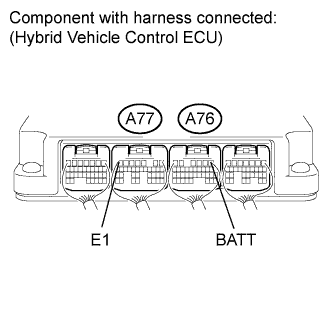
CHECK CONNECTOR CONNECTION CONDITION (HYBRID VEHICLE CONTROL ECU CONNECTOR)
-
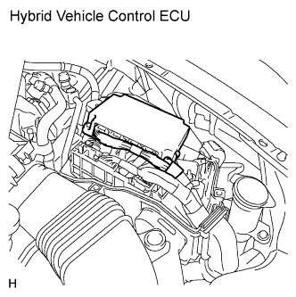
Check the connections of the hybrid vehicle control ECU connectors.
OK The connectors are connected securely and there are no contact problems.
NG 
CONNECT SECURELY
OK 
-
-
CHECK HARNESS AND CONNECTOR (HYBRID VEHICLE CONTROL ECU - IGCT2 FUSE)
-
Turn the power switch off.
-
Measure the voltage according to the value(s) in the table below.
Standard voltage Tester Connection Switch Condition Specified Condition A76-1 (BATT) - A77-7 (E1) Power switch off 11 to 14 V
NG 
CHECK FUSES (IGCT2 FUSE) Click here
OK 
REPLACE HYBRID VEHICLE CONTROL ECU Click here
-
-
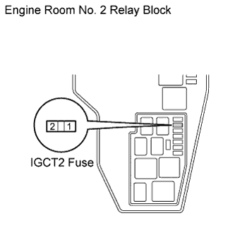
CHECK FUSES (IGCT2 FUSE)
-
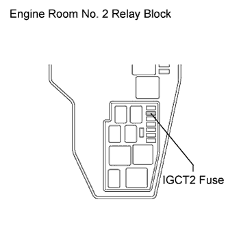
Check if there is an open circuit in the fuse (IGCT2) in the engine room No. 2 relay block.
OK There is no open circuit in the fuse (IGCT2).
NG
REPLACE FUSES (IGCT2)
OK
-
-
CHECK HARNESS AND CONNECTOR (IGCT2 FUSE - BATTERY POSITIVE TERMINAL)
-
Disconnect the auxiliary battery negative terminal cable.
-
Disconnect the auxiliary battery positive terminal cable.
-
Measure the resistance according to the value(s) in the table below.
Standard resistance (Check for open) Tester Connection Switch Condition Specified Condition Engine room No. 2 relay block IGCT2 fuse terminal 1 - Positive (+) battery terminal Power switch off Below 1 Ω Standard resistance (Check for short) Tester Connection Switch Condition Specified Condition Engine room No. 2 relay block IGCT2 fuse terminal 1 - Body ground Power switch off 10 kΩ or higher
NG
REPAIR OR REPLACE HARNESS OR CONNECTOR
OK
-
-
CHECK HARNESS AND CONNECTOR (IGCT2 FUSE - HYBRID VEHICLE CONTROL ECU)
-
Disconnect connector A76 from the hybrid vehicle control ECU.
-
Measure the resistance according to the value(s) in the table below.
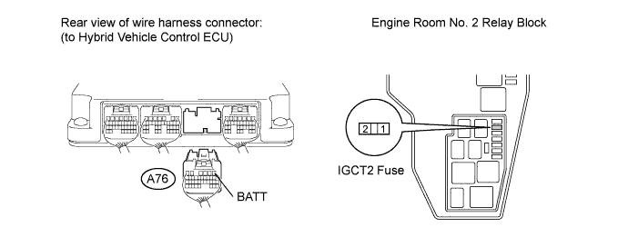
Standard resistance Tester Connection Switch Condition Specified Condition Engine room No. 2 relay block IGCT2 fuse terminal 2 - A76-1 (BATT) Power switch off Below 1 Ω
NG
REPAIR OR REPLACE HARNESS OR CONNECTOR
OK
REPLACE HYBRID VEHICLE CONTROL ECU Click here
-