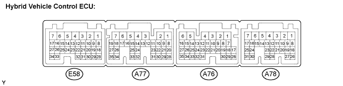
HYBRID CONTROL SYSTEM TERMINALS OF ECU

| Terminal No. (Symbol) |
Wiring Color | Terminal Description | Condition | Standard Voltage (V) |
|---|---|---|---|---|
| E58-1 (+BS) - A77-7 (E1) | BR - W-B | Park/neutral position switch power source | Power switch on (IG) | 10 to 14 |
| E58-2 (SL1-) - E58-3 (SL1+) | L - B | SL1 solenoid valve signal | During active test | Pulse generation (Waveform 1) |
| E58-4 (SMRG) - A77-7 (E1) | R - W-B | System main relay | Power switch on (IG) to on (READY) | Pulse generation (Waveform 2) |
| E58-5 (SMRB) - A77-7 (E1) | G - W-B | System main relay | Power switch on (IG) to on (READY) | Pulse generation (Waveform 2) |
| E58-8 (SP) - A77-7 (E1) | L-Y - W-B | SP solenoid valve signal | During active test | 10 to 14 |
| E58-10 (SL2-) - E58-11 (SL2+) | Y - P-L | SL2 solenoid valve signal | During active test | Pulse generation (Waveform 3) |
| E58-12 (MJ) - A77-7 (E1) | L - W-B | Park/neutral position switch signal | Power switch on (IG), shift lever in P, R, N or D position | 10 to 14 |
| E58-14 (D) - A77-7 (E1) | R - W-B | Park/neutral position switch signal | Power switch on (IG), shift lever in D or S position | 10 to 14 |
| E58-14 (D) - A77-7 (E1) | R - W-B | Park/neutral position switch signal | Power switch on (IG), shift lever not in D or S position | 0 to 1.5 |
| E58-15 (N) - A77-7 (E1) | W - W-B | Park/neutral position switch signal | Power switch on (IG), shift lever not in N position | 10 to 14 |
| E58-15 (N) - A77-7 (E1) | W - W-B | Park/neutral position switch signal | Power switch on (IG), shift lever not in N position | 1.5 to 3.0 |
| E58-16 (R) - A77-7 (E1) | P - W-B | Park/neutral position switch signal | Power switch on (IG), shift lever in R position | 10 to 14 |
| E58-16 (R) - A77-7 (E1) | P - W-B | Park/neutral position switch signal | Power switch on (IG), shift lever not in R position | 0 to 1.5 |
| E58-17 (P) - A77-7 (E1) | G - W-B | Park/neutral position switch signal | Power switch on (IG), shift lever in P position | 10 to 14 |
| E58-17 (P) - A77-7 (E1) | G - W-B | Park/neutral position switch signal | Power switch on (IG), shift lever not in P position | 0 to 1.5 |
| E58-18 (PB1) - A77-7 (E1) | R - W-B | Pressure switch 1 | Power switch on (READY) | 10 to 14 |
| E58-19 (PB2) - A77-7 (E1) | W - W-B | Pressure switch 2 | Power switch on (READY) | 10 to 14 |
| E58-20 (PB3) - A77-7 (E1) | B - W-B | Pressure switch 3 | Power switch on (READY) | 10 to 14 |
| E58-21 (ITE) - A77-7 (E1) | R - W-B | A/C communication signal | Power switch on (READY), air conditioning system stopped | Pulse generation (Waveform 4) |
| E58-22 (MMTG) - E58-23 (MMT) | P - Y | Motor temperature sensor | Power switch on (IG), temperature 25°C (77°F) | 1.9 to 2.8 |
| E58-22 (MMTG) - E58-23 (MMT) | P - Y | Motor temperature sensor | Power switch on (IG), temperature 60°C (140°F) | 1.1 to 1.8 |
| E58-24 (GMTG) - E58-25 (GMT) | R - W | Generator temperature sensor | Power switch on (IG), temperature 25°C (77°F) | 1.9 to 2.8 |
| E58-24 (GMTG) - E58-25 (GMT) | R - W | Generator temperature sensor | Power switch on (IG), temperature 60°C (140°F) | 1.1 to 1.8 |
| E58-26 (FD) - A77-7 (E1) | B - W-B | Park/neutral position switch signal | Power switch on (IG), shift lever in D or S position | 10 to 14 |
| E58-26 (FD) - A77-7 (E1) | B - W-B | Park/neutral position switch signal | Power switch on (IG), shift lever not in D or S position | 0 to 1.5 |
| E58-27 (RV) - A77-7 (E1) | V - W-B | Park/neutral position switch signal | Power switch on (IG), shift lever in R position | 10 to 14 |
| E58-27 (RV) - A77-7 (E1) | V - W-B | Park/neutral position switch signal | Power switch on (IG), shift lever not in R or S position | 0 to 1.5 |
| E58-28 (SP2-) - E58-29 (SP2+) | R - G | Transmission revolution sensor signal | Driving at approximately 55 km/h (34 mph) with power switch on (READY) | Pulse generation (Waveform 5) |
| E58-30 (CLK) - A77-7 (E1) | BR - W-B | A/C communication signal | Power switch on (READY), air conditioning system stopped | Pulse generation (Waveform 4) |
| E58-31 (STB) - A77-7 (E1) | L - W-B | A/C communication signal | Power switch on (READY), air conditioning system stopped | Pulse generation (Waveform 4) |
| E58-32 (ETI) - A77-7 (E1) | B - W-B | A/C communication signal | Power switch on (READY), air conditioning system stopped | Pulse generation (Waveform 4) |
| E58-33 (THO) - A76-5 (E2) | R-Y - W (*1) R-Y - BR (*2) |
Transmission fluid temperature sensor | Power switch on (IG), temperature 25°C (77°F) | 2.2 to 2.8 |
| E58-34 (TOPM) - A76-5 (E2) | L - W (*1) L - BR (*2) |
Oil pump motor temperature sensor | Power switch on (IG), temperature 25°C (77°F) | 2.4 to 3.1 |
| A77-1 (STP) - A77-7 (E1) | L - W-B | Stop light switch | Brake pedal depressed | 10 to 14 |
| A77-1 (STP) - A77-7 (E1) | L - W-B | Stop light switch | Brake pedal released | 0 to 1.5 |
| A77-5 (WP) - A77-7 (E1) | B - W-B | A/C WP relay signal | Power switch on (READY) | Below 2 |
| A77-8 (CAN+) - A77-7 (E1) | B - W-B | CAN communication system | Power switch on (IG) | Pulse generation (Waveform 6) |
| A77-9 (CAN-) - A77-7 (E1) | W - W-B | CAN communication system | Power switch on (IG) | Pulse generation (Waveform 6) |
| A77-10 (SFTD) - A77-7 (E1) | Y - W-B | Transmission control switch | Power switch on (IG), shift lever in S position | 10 to 14 |
| A77-10 (SFTD) - A77-7 (E1) | Y - W-B | Transmission control switch | Power switch on (IG), Sports shift in (-) position | 0 to 1.5 |
| A77-11 (SFTU) - A77-7 (E1) | L - W-B | Transmission control switch | Power switch on (IG), shift lever in S position | 10 to 14 |
| A77-11 (SFTU) - A77-7 (E1) | L - W-B | Transmission control switch | Power switch on (IG), Sports shift in (+) position | 0 to 1.5 |
| A77-12 (M) - A77-7 (E1) | B - W-B | Transmission control switch | Power switch on (IG), shift lever in S position | 10 to 14 |
| A77-12 (M) - A77-7 (E1) | B - W-B | Transmission control switch | Power switch on (IG), shift lever not in S position | 0 to 1.5 |
| A77-13 (NEI) - A77-7 (E1) | G - W-B | Crankshaft position signal | Power switch on (READY), engine started | Pulse generation (Waveform 7) |
| A77-14 (GI) - A77-7 (E1) | BR - W-B | Camshaft position signal | Power switch on (READY), engine started | Pulse generation (Waveform 8) |
| A77-21 (PSOK) - A77-7 (E1) | V - W-B | Electric power steering permission signal | Power switch on (READY) | Pulse generation (Waveform 9) |
| A77-24 (TC) - A77-7 (E1) | P - W-B (*1) V - W-B (*2) |
Diagnosis terminal | Power switch on (IG) | 10 to 14 |
| A77-25 (SI0) - A77-7 (E1) | GR - W-B | No. 2 HV battery blower fan | Power switch on (IG), during active test | Pulse generation (Waveform 10) |
| A77-26 (FCTL) - A77-7 (E1) | BR - W-B | Cooling fan relay | Power switch on (IG) | 10 to 14 |
| A77-30 (THB) - A76-5 (E2) | P - W (*1) P - BR (*2) |
Auxiliary battery temperature sensor signal | Auxiliary battery temperature 60°C (140°F) | 0.7 to 1.3 |
| A77-30 (THB) - A76-5 (E2) | P - W (*1) P - BR (*2) |
Auxiliary battery temperature sensor signal | Auxiliary battery temperature 25°C (77°F) | 1.8 to 2.5 |
| A77-32 (IMI) - A77-7 (E1) | L - W-B | Immobiliser communication | Immobiliser communicating | Pulse generation (Waveform 11) |
| A77-33 (IMO) - A77-7 (E1) | B - W-B | Immobiliser communication | Immobiliser communicating | Pulse generation (Waveform 11) |
| A77-35 (SI1) - A77-7 (E1) | LG - W-B | No. 1 HV battery blower fan | Power switch on (IG), during active test | Pulse generation (Waveform 12) |
| A76-1 (BATT) - A77-7 (E1) | B-W - W-B | Constant power source | Always | 10 to 14 |
| A76-3 (MREL) - A77-7 (E1) | G - W-B | Main relay | Power switch on (IG) | 10 to 14 |
| A76-4 (IGSW) - A77-7 (E1) | R - W-B | IG signal | Power switch on (IG) | 10 to 14 |
| A76-8 (DCIM) - A77-7 (E1) | BE - W-B | Hybrid vehicle converter load status | Power switch on (READY), PTC heater operation is possible |
5.2 to 8.8 |
| A76-8 (DCIM) - A77-7 (E1) | BE - W-B | Hybrid vehicle converter load status | Power switch on (READY), PTC heater operation prohibited |
1.4 to 4.6 |
| A76-11 (CA2H) - A77-7 (E1) | B - W-B | CAN communication system | Power switch on (IG) | Pulse generation (Waveform 13) |
| A76-12 (CA2L) - A77-7 (E1) | W - W-B | CAN communication system | Power switch on (IG) | Pulse generation (Waveform 13) |
| A76-13 (CA3H) - A77-7 (E1) | B - W-B | CAN communication system | Power switch on (IG) | Pulse generation (Waveform 14) |
| A76-14 (CA3L) - A77-7 (E1) | W - W-B | CAN communication system | Power switch on (IG) | Pulse generation (Waveform 14) |
| A76-15 (CANH) - A77-7 (E1) | Y - W-B | CAN communication system | Power switch on (IG) | Pulse generation (Waveform 15) |
| A76-16 (CANL) - A77-7 (E1) | L - W-B | CAN communication system | Power switch on (IG) | Pulse generation (Waveform 15) |
| A76-20 (VPA1) - A76-19 (EP1) | R - Y | Accelerator pedal position sensor (for accelerator pedal position detection) | Power switch on (IG), accelerator pedal released | 0.4 to 1.4 |
| A76-20 (VPA1) - A76-19 (EP1) | R - Y | Accelerator pedal position sensor (for accelerator pedal position detection) | Power switch on (IG), engine stopped, shift lever in P position, accelerator pedal fully depressed | 2.6 to 4.5 |
| A76-21 (VPA2) - A76-18 (EP2) | G - L | Accelerator pedal position sensor (for accelerator pedal position detection) | Power switch on (IG), accelerator pedal released | 1.0 to 2.2 |
| A76-21 (VPA2) - A76-18 (EP2) | G - L | Accelerator pedal position sensor (for accelerator pedal position detection) | Power switch on (IG), engine stopped, shift lever in P position, accelerator pedal fully depressed | 3.4 to 5.3 |
| A76-22 (VCP1) - A76-19 (EP1) | W - Y | Accelerator pedal position sensor power source (for VPA1) | Power switch on (IG) | 4.5 to 5.5 |
| A76-23 (VCP2) - A76-18 (EP2) | B - L | Accelerator pedal position sensor power source (for VPA2) | Power switch on (IG) | 4.5 to 5.5 |
| A76-24 (OPM2) - A77-7 (E1) | V - W-B | Oil pump motor | Power switch on (IG) | 10 to 14 |
| A76-25 (SMRP) - A77-7 (E1) | G - W-B | System main relay | Power switch on (IG) to on (READY) | Pulse generation (Waveform 2) |
| A76-26 (NODD) - A77-7 (E1) | L - W-B | DC/DC operation | Converter operating normally | 5 to 7 |
| A76-26 (NODD) - A77-7 (E1) | L - W-B | DC/DC operation | Converter not operating normally | 2 to 4 |
| A76-26 (NODD) - A77-7 (E1) | L - W-B | DC/DC operation | Converter operation prohibited | 0.1 to 0.5 |
| A76-27 (VLO) - A77-7 (E1) | R - W-B | DC/DC operation monitor / voltage change signal | Power switch on (IG) | Pulse generation (Waveform 16) |
| A76-32 (OPM1) - A77-7 (E1) | W - W-B | Oil pump motor | Power switch on (IG) | Pulse generation (Waveform 17) |
| A76-33 (OPST) - A77-7 (E1) | B - W-B | Oil pump motor | Power switch on (IG) | Pulse generation (Waveform 18) |
| A78-1 (+B1) - A77-7 (E1) | B - W-B | Power source | Power switch on (IG) | 10 to 14 |
| A78-2 (+B2) - A77-7 (E1) | L - W-B | Power source | Power switch on (IG) | 10 to 14 |
| A78-6 (ST1-) - A77-7 (E1) | V - W-B | Brake cancel switch | Power switch on (IG), brake pedal depressed | 0 to 1.5 |
| A78-6 (ST1-) - A77-7 (E1) | V - W-B | Brake cancel switch | Power switch on (IG), brake pedal released | 10 to 14 |
| A78-8 (CLK+) - A77-7 (E1) | Y - W-B | MG communication clock signal | Power switch on (READY) | Pulse generation (Waveform 19) |
| A78-9 (CLK-) - A77-7 (E1) | L - W-B | MG communication clock signal | Power switch on (READY) | Pulse generation (Waveform 19) |
| A78-10 (HTM+) - A77-7 (E1) | R - W-B | Communication from HV to MG | Power switch on (READY) | Pulse generation (Waveform 20) |
| A78-11 (HTM-) - A77-7 (E1) | G - W-B | Communication from HV to MG | Power switch on (READY) | Pulse generation (Waveform 20) |
| A78-13 (MTH+) - A77-7 (E1) | B - W-B | Communication from MG to HV | Power switch on (READY) | Pulse generation (Waveform 21) |
| A78-14 (MTH-) - A77-7 (E1) | W - W-B | Communication from MG to HV | Power switch on (READY) | Pulse generation (Waveform 21) |
| A78-16 (REQ+) - A77-7 (E1) | W - W-B | MG communication request signal | Power switch on (READY) | Pulse generation (Waveform 22) |
| A78-17 (REQ-) - A77-7 (E1) | B - W-B | MG communication request signal | Power switch on (READY) | Pulse generation (Waveform 22) |
| A78-19 (BTH-) - A77-7 (E1) | BR - W-B | Communication from battery to HV | Power switch on (READY) | Pulse generation (Waveform 23) |
| A78-20 (BTH+) - A77-7 (E1) | Y - W-B | Communication from battery to HV | Power switch on (READY) | Pulse generation (Waveform 23) |
| A78-21 (ILK) - A77-7 (E1) | GR - W-B | Interlock switch | Power switch on (IG), inverter cover and service plug grip installed correctly | 0 to 1.5 |
| A78-21 (ILK) - A77-7 (E1) | GR - W-B | Interlock switch | Power switch on (IG), inverter cover and service plug grip detached | 10 to 14 |
| A78-23 (IWP) - A77-7 (E1) | Y - W-B | HV water pump signal | Power switch on (READY) | Pulse generation (Waveform 24) |
| A78-25 (HSDN) - A77-7 (E1) | B - W-B | MG shutdown signal | Power switch on (READY) | 0 to 1.5 |
| A78-28 (ST2) - A77-7 (E1) | B - W-B | Starter signal | Power switch on (IG) | 0 to 1.5 |
| A78-29 (RDY) - A77-7 (E1) | W - W-B | READY state | Power switch on (IG) to on (READY) | Pulse generation (Waveform 25) |
| A78-30 (SPDI) - A77-7 (E1) | V - W-B | Vehicle speed signal | Approximately 20 km/h (12 mph) | Pulse generation (Waveform 26) |
| A78-31 (ABFS) - A77-7 (E1) | Y - W-B | Airbag activation signal | Power switch on (READY) (2 seconds after ACC ON) | Pulse generation (Waveform 27) |
*1: LHD
*2: RHD
-
Oscilloscope waveforms
Tech Tips
Oscilloscope waveform samples are provided here for informational purposes. Noise and fluttering waveforms have been omitted.
-
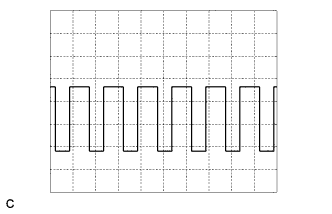
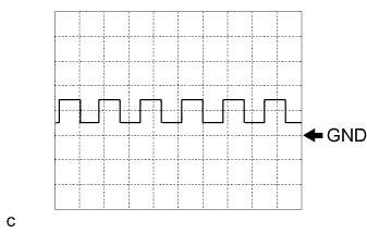
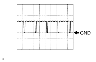
Waveform 1 (SL1 solenoid valve signal)
Item Contents Terminal E58-2 (SL1-) - E58-3 (SL1+) Equipment Setting 5 V/DIV., 2 ms./DIV. Condition During active test -
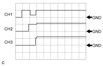
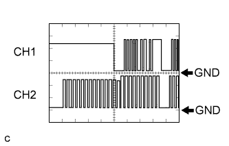
Waveform 2 (system main relay operation signal)
Item Contents Terminal CH1: A76-25 (SMRP) - A77-7 (E1)
CH2: E58-5 (SMRB) - A77-7 (E1)
CH3: E58-4 (SMRG) - A77-7 (E1)
Equipment Setting 10 V/DIV., 500 ms./DIV. Condition Power switch on (IG) → Power switch on (READY) -
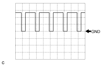
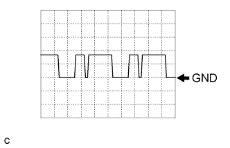
Waveform 3 (SL2 solenoid valve signal)
Item Contents Terminal E58-10 (SL2-) - E58-11 (SL2+) Equipment Setting 5 V/DIV., 2 ms./DIV. Condition During active test -
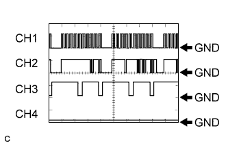
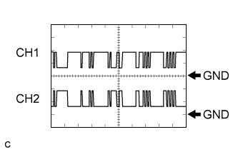
Waveform 4 (A/C communication signal)
Item Contents Terminal CH1: E58-30 (CLK) - A77-7 (E1)
CH2: E58-21 (ITE) - A77-7 (E1)
CH3: E58-32 (ETI) - A77-7 (E1)
CH4: E58-31 (STB) - A77-7 (E1)
Equipment Setting 10 V/DIV., 100 ms./DIV. Condition Power switch on (READY) with air conditioning system stopped Tech Tips
The waveform will vary depending on the content of the digital communication (digital signal).
-
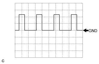
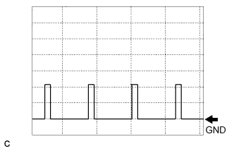
Waveform 5 (transmission revolution signal)
Item Contents Terminal E58-28 (SP2-) - E58-29 (SP2+) Equipment Setting 2 V/DIV., 2 ms./DIV. Condition Driving at approximately 55 km/h (34 mph) with power switch on (READY) Tech Tips
The higher the vehicle speed, the shorter the cycle.
-
Waveform 6 (CAN communication signal)
Item Contents Terminal CH1: A77-8 (CAN+) - A77-7 (E1)
CH2: A77-9 (CAN-) - A77-7 (E1)
Equipment Setting 1 V/DIV., 20 μs./DIV. Condition Power switch on (IG) Tech Tips
The waveform will vary depending on the content of the digital communication (digital signal).
-
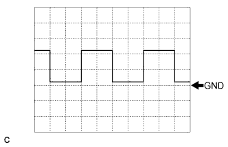
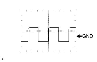
Waveform 7 (NEI signal)
Item Contents Terminal A77-13 (NEI) - A77-7 (E1) Equipment Setting 5 V/DIV., 1 ms./DIV. Condition Power switch on (READY) with engine running Tech Tips
The pulse cycle becomes shorter as the engine speed increases.
-
Waveform 8 (GI signal)
Item Contents Terminal A77-14 (GI) - A77-7 (E1) Equipment Setting 5 V/DIV., 20 ms./DIV. Condition Power switch on (READY) with engine running Tech Tips
The pulse cycle becomes shorter as the engine speed increases.
-
Waveform 9 (CAN communication signal)
Item Contents Terminal A77-21 (PSOK) - A77-7 (E1) Equipment Setting 5 V/DIV., 50 ms./DIV. Condition Power switch on (READY) -
Waveform 10 (No. 2 HV battery blower fan operation signal)
Item Contents Terminal A77-25 (SI0) - A77-7 (E1) Equipment Setting 5 V/DIV., 100 ms./DIV. Condition Power switch on (IG) during active test -
Waveform 11 (immobiliser communication signal)
Item Contents Terminal CH1: A77-33 (IMO) - A77-7 (E1)
CH2: A77-32 (IMI) - A77-7 (E1)
Equipment Setting 5 V/DIV., 200 ms./DIV. Condition Power switch off → Power switch on (IG) → Power switch on (READY) -
Waveform 12 (No. 1 HV battery blower fan operation signal)
Item Contents Terminal A77-35 (SI1) - A77-7 (E1) Equipment Setting 5 V/DIV., 100 ms./DIV. Condition Power switch on (IG) during active test -
Waveform 13 (CAN communication signal)
Item Contents Terminal CH1: A76-11 (CA2H) - A77-7 (E1)
CH2: A76-12 (CA2L) - A77-7 (E1)
Equipment Setting 1 V/DIV., 20 μs./DIV. Condition Power switch on (IG) Tech Tips
The waveform will vary depending on the content of the digital communication (digital signal).
-
Waveform 14 (CAN communication signal)
Item Contents Terminal CH1: A76-13 (CA3H) - A77-7 (E1)
CH2: A76-14 (CA3L) - A77-7 (E1)
Equipment Setting 1 V/DIV., 20 μs./DIV. Condition Power switch on (IG) Tech Tips
The waveform will vary depending on the content of the digital communication (digital signal).
-
Waveform 15 (CAN communication signal)
Item Contents Terminal CH1: A76-15 (CANH) - A77-7 (E1)
CH2: A76-16 (CANL) - A77-7 (E1)
Equipment Setting 1 V/DIV., 20 μs./DIV. Condition Power switch on (IG) Tech Tips
The waveform will vary depending on the content of the digital communication (digital signal).
-
Waveform 16 (VLO signal)
Item Contents Terminal A76-27 (VLO) - A77-7 (E1) Equipment Setting 5 V/DIV., 50 ms./DIV. Condition Power switch on (IG) Tech Tips
The cycle will vary depending on the specified voltage of the hybrid vehicle converter.
-
Waveform 17 (oil pump motor signal)
Item Contents Terminal A76-32 (OPM1) - A77-7 (E1) Equipment Setting 5 V/DIV., 500 μs./DIV. Condition Power switch on (IG) -
Waveform 18 (oil pump motor signal)
Item Contents Terminal A76-33 (OPST) - A77-7 (E1) Equipment Setting 5 V/DIV., 5 ms./DIV. Condition Power switch on (IG) -
Waveform 19 (MG communication clock signal)
Item Contents Terminal CH1: A78-8 (CLK+) - A77-7 (E1)
CH2: A78-9 (CLK-) - A77-7 (E1)
Equipment Setting 1 V/DIV., 1 μs./DIV. Condition Power switch on (READY) -
Waveform 20 (communication signal from hybrid vehicle control ECU to MG ECU)
Item Contents Terminal CH1: A78-10 (HTM+) - A77-7 (E1)
CH2: A78-11 (HTM-) - A77-7 (E1)
Equipment Setting 1 V/DIV., 200 μs./DIV. Condition Power switch on (READY) Tech Tips
The waveform will vary depending on the content of the digital communication (digital signal).
-
Waveform 21 (communication signal from MG ECU to hybrid vehicle control ECU)
Item Contents Terminal CH1: A78-13 (MTH+) - A77-7 (E1)
CH2: A78-14 (MTH-) - A77-7 (E1)
Equipment Setting 1 V/DIV., 200 μs./DIV. Condition Power switch on (READY) Tech Tips
The waveform will vary depending on the content of the digital communication (digital signal).
-

Waveform 22 (MG communication request signal)
Item Contents Terminal CH1: A78-16 (REQ+) - A77-7 (E1)
CH2: A78-17 (REQ-) - A77-7 (E1)
Equipment Setting 1 V/DIV., 1 ms./DIV. Condition Power switch on (READY) -
Waveform 23 (communication signal from battery smart unit to hybrid vehicle control ECU)
Item Contents Terminal CH1: A78-20 (BTH+) - A77-7 (E1)
CH2: A78-19 (BTH-) - A77-7 (E1)
Equipment Setting 2 V/DIV., 500 μs./DIV. Condition Power switch on (IG) Tech Tips
The waveform will vary depending on the content of the digital communication (digital signal).
-
Waveform 24 (HV water pump signal)
Item Contents Terminal A78-23 (IWP) - A77-7 (E1) Equipment Setting 5 V/DIV., 100 ms./DIV. Condition Power switch on (READY) -
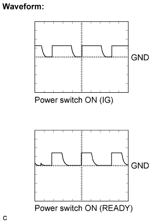
Waveform 25 (READY signal)
Item Contents Terminal A78-29 (RDY) - A77-7 (E1) Equipment Setting 10 V/DIV., 10 ms./DIV. Condition Power switch on (IG) / Power switch on (READY) -
Waveform 26 (vehicle speed signal)
Item Contents Terminal A78-30 (SPDI) - A77-7 (E1) Equipment Setting 5 V/DIV., 20 ms./DIV. Condition Driving at approximately 20 km/h (12 mph) with power switch on (READY) Tech Tips
The higher the vehicle speed, the shorter the cycle.
-
Waveform 27 (airbag deployment signal)
Item Contents Terminal A78-31 (ABFS) - A77-7 (E1) Equipment Setting 5 V/DIV., 500 ms./DIV. Condition Power switch on (READY)
LHD: Terminal No.
(Symbol)
Wiring Color Terminal Description Condition Standard Voltage
(V)
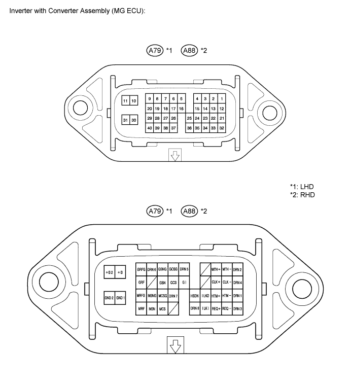
A79-10 (+B) - A79-30 (GND1) B - W-B MG - ECU battery Power switch on (IG) 10 to 14 A79-11 (+B2) - A79-30 (GND1) B - W-B MG - ECU battery Power switch on (IG) 10 to 14 A79-14 (CLK+) - A79-30 (GND1) Y - W-B Communication clock signal Power switch on (IG) 10 to 14 A79-13 (CLK-) - A79-30 (GND1) L - W-B Communication clock signal Power switch on (IG) 10 to 14 A79-40 (MRF) - A79-29 (MRFG) B - G Motor resolver signal Motor resolver stopped or running Pulse generation (Waveform 1) A79-24 (ILKO) - A79-30 (GND1) W - W-B Interlock switch signal Power switch on (IG), inverter cover and service plug grip installed correctly Below 1 A79-24 (ILKO) - A79-30 (GND1) W - W-B Interlock switch signal Power switch on (IG), inverter cover or service plug grip detached 10 to 14 A79-34 (REQ+) - A79-30 (GND1) W - W-B Communication request signal Power switch on (IG) Pulse generation
(Waveform 2)
A79-23 (HTM+) - A79-30 (GND1) R - W-B Communication signal from HV to MG Power switch on (IG) Pulse generation
(Waveform 3)
A79-22 (HTM-) - A79-30 (GND1) G - W-B Communication signal from HV to MG Power switch on (IG) Pulse generation
(Waveform 3)
A79-38 (MCS) - A79-27 (MCSG) W - Y Motor resolver signal Motor resolver stopped or running Pulse generation
(Waveform 1)
A79-39 (MSN) - A79-28 (MSNG) L - R Motor resolver signal Motor resolver stopped or running Pulse generation
(Waveform 1)
A79-35 (ILKI) - A79-30 (GND1) GR - W-B Interlock switch signal Power switch on (IG), inverter cover and service plug grip installed correctly Below 1 A79-35 (ILKI) - A79-30 (GND1) GR - W-B Interlock switch signal Power switch on (IG), inverter cover or service plug grip detached 10 to 14 A79-33 (REQ-) - A79-30 (GND1) B - W-B Communication request signal Power switch on (IG) Pulse generation
(Waveform 2)
A79-16 (GI) - A79-30 (GND1) B - W-B GI signal Power switch on (READY), engine started Pulse generation
(Waveform 4)
A79-18 (GSN) - A79-7 (GSNG) R - W Generator resolver signal Generator resolver stopped or running Pulse generation
(Waveform 5)
A79-17 (GCS) - A79-6 (GCSG) Y - B Generator resolver signal Generator resolver stopped or running Pulse generation
(Waveform 5)
A79-3 (MTH+) - A79-30 (GND1) B - W-B Communication signal from MG to HV Previously corrected Pulse generation
(Waveform 6
A79-2 (MTH-) - A79-30 (GND1) W - W-B Communication signal from MG to HV Previously corrected Pulse generation
(Waveform 6)
A79-25 (HSDN) - A79-30 (GND1) B - W-B MG shutdown signal Previously corrected Below 1 A79-20 (GRF) - A79-9 (GRFG) G - L Generator resolver signal Generator resolver stopped or running Pulse generation
(Waveform 5)
RHD: Terminal No.
(Symbol)
Wiring Color Terminal Description Condition Standard Voltage
(V)
A88-10 (+B) - A88-30 (GND1) B - W-B MG - ECU battery Power switch on (IG) 10 to 14 A88-11 (+B2) - A88-30 (GND1) B - W-B MG - ECU battery Power switch on (IG) 10 to 14 A88-14 (CLK+) - A88-30 (GND1) Y - W-B Communication clock signal Power switch on (IG) 10 to 14 A88-13 (CLK-) - A88-30 (GND1) L - W-B Communication clock signal Power switch on (IG) 10 to 14 A88-40 (MRF) - A88-29 (MRFG) B - G Motor resolver signal Motor resolver stopped or running Pulse generation (Waveform 1) A88-24 (ILKO) - A88-30 (GND1) W - W-B Interlock switch signal Power switch on (IG), inverter cover and service plug grip installed correctly Below 1 A88-24 (ILKO) - A88-30 (GND1) W - W-B Interlock switch signal Power switch on (IG), inverter cover or service plug grip detached 10 to 14 A88-34 (REQ+) - A88-30 (GND1) W - W-B Communication request signal Power switch on (IG) Pulse generation
(Waveform 2)
A88-23 (HTM+) - A88-30 (GND1) R - W-B Communication signal from HV to MG Power switch on (IG) Pulse generation
(Waveform 3)
A88-22 (HTM-) - A88-30 (GND1) G - W-B Communication signal from HV to MG Power switch on (IG) Pulse generation
(Waveform 3)
A88-38 (MCS) - A88-27 (MCSG) W - Y Motor resolver signal Motor resolver stopped or running Pulse generation
(Waveform 1)
A88-39 (MSN) - A88-28 (MSNG) L - R Motor resolver signal Motor resolver stopped or running Pulse generation
(Waveform 1)
A88-35 (ILKI) - A88-30 (GND1) GR - W-B Interlock switch signal Power switch on (IG), inverter cover and service plug grip installed correctly Below 1 A88-35 (ILKI) - A88-30 (GND1) GR - W-B Interlock switch signal Power switch on (IG), inverter cover or service plug grip detached 10 to 14 A88-33 (REQ-) - A88-30 (GND1) B - W-B Communication request signal Power switch on (IG) Pulse generation
(Waveform 2)
A88-16 (GI) - A88-30 (GND1) B - W-B GI signal Power switch on (READY), engine started Pulse generation
(Waveform 4)
A88-18 (GSN) - A88-7 (GSNG) R - W Generator resolver signal Generator resolver stopped or running Pulse generation
(Waveform 5)
A88-17 (GCS) - A88-6 (GCSG) Y - B Generator resolver signal Generator resolver stopped or running Pulse generation
(Waveform 5)
A88-3 (MTH+) - A88-30 (GND1) B - W-B Communication signal from MG to HV Previously corrected Pulse generation
(Waveform 6
A88-2 (MTH-) - A88-30 (GND1) W - W-B Communication signal from MG to HV Previously corrected Pulse generation
(Waveform 6)
A88-25 (HSDN) - A88-30 (GND1) B - W-B MG shutdown signal Previously corrected Below 1 A88-20 (GRF) - A88-9 (GRFG) G - L Generator resolver signal Generator resolver stopped or running Pulse generation
(Waveform 5)
Note
Do not measure the voltage or waveform directly at the sealed side of the inverter with converter assembly connector. Doing so may damage the connector because the connector is waterproof.
-
-
Oscilloscope waveforms
Tech Tips
Oscilloscope waveform samples are provided here for informational purposes. Noise and fluttering waveforms have been omitted.
-
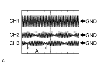
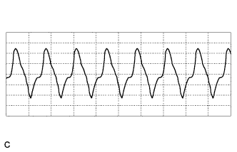
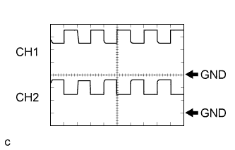
Waveform 1 (motor resolver signal)
LHD: Item Contents Terminal CH1: A79-40 (MRF) - A79-29 (MRFG)
CH2: A79-39 (MSN) - A79-28 (MSNG)
CH3: A79-38 (MCS) - A79-27 (MCSG)
Equipment Setting CH1: 10 V/DIV., 1 ms./DIV.
CH2, CH3: 5 V/DIV., 1 ms./DIV.
Condition Resolver running RHD: Item Contents Terminal CH1: A88-40 (MRF) - A88-29 (MRFG)
CH2: A88-39 (MSN) - A88-28 (MSNG)
CH3: A88-38 (MCS) - A88-27 (MCSG)
Equipment Setting CH1: 10 V/DIV., 1 ms./DIV.
CH2, CH3: 5 V/DIV., 1 ms./DIV.
Condition Resolver running Tech Tips
Pulse cycle A becomes shorter as the rotor speed increases.
-
Waveform 2 (MG ECU communication request signal)
LHD: Item Contents Terminal CH1: A79-34 (REQ+) - A79-30 (GND1)
CH2: A79-33 (REQ-) - A79-30 (GND1)
Equipment Setting 1 V/DIV., 1 ms./DIV. Condition Power switch on (IG) RHD: Item Contents Terminal CH1: A88-34 (REQ+) - A88-30 (GND1)
CH2: A88-33 (REQ-) - A88-30 (GND1)
Equipment Setting 1 V/DIV., 1 ms./DIV. Condition Power switch on (IG) -
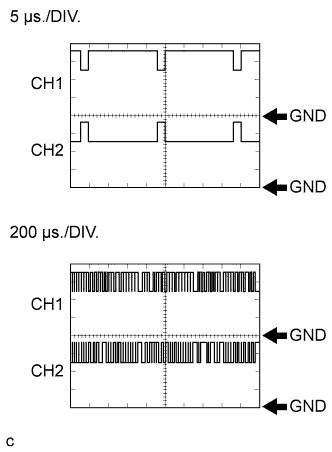
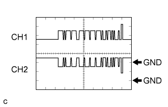
Waveform 3 (communication signal from hybrid vehicle control ECU to MG ECU)
LHD: Item Contents Terminal CH1: A79-23 (HTM+) - A79-30 (GND1)
CH2: A79-22 (HTM-) - A79-30 (GND1)
Equipment Setting 1 V/DIV., 5 μs./DIV.
1 V/DIV., 200 μs./DIV.
Condition Power switch on (IG) RHD: Item Contents Terminal CH1: A88-23 (HTM+) - A88-30 (GND1)
CH2: A88-22 (HTM-) - A88-30 (GND1)
Equipment Setting 1 V/DIV., 5 μs./DIV.
1 V/DIV., 200 μs./DIV.
Condition Power switch on (IG) Tech Tips
The waveform will vary depending on the content of the digital communication (digital signal).
-
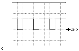
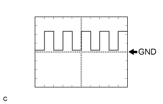
Waveform 4 (GI signal)
LHD: Item Contents Terminal CH1: A79-16 (GI) - A79-30 (GND1) Equipment Setting 5 V/DIV., 20 ms./DIV. Condition Power switch on (READY) with engine running RHD: Item Contents Terminal CH1: A88-16 (GI) - A88-30 (GND1) Equipment Setting 5 V/DIV., 20 ms./DIV. Condition Power switch on (READY) with engine running Tech Tips
The pulse cycle becomes shorter as the engine speed increases.
-
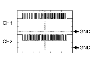
Waveform 5 (generator resolver signal)
LHD: Item Contents Terminal CH1: A79-20 (GRF) - A79-9 (GRFG)
CH2: A79-18 (GSN) - A79-7 (GSNG)
CH2: A79-17 (GCS) - A79-6 (GCSG)
Equipment Setting CH1: 10 V/DIV., 1 ms./DIV.
CH2, CH3: 5 V/DIV., 1 ms./DIV.
Condition Resolver running RHD: Item Contents Terminal CH1: A88-20 (GRF) - A88-9 (GRFG)
CH2: A88-18 (GSN) - A88-7 (GSNG)
CH2: A88-17 (GCS) - A88-6 (GCSG)
Equipment Setting CH1: 10 V/DIV., 1 ms./DIV.
CH2, CH3: 5 V/DIV., 1 ms./DIV.
Condition Resolver running Tech Tips
Pulse cycle A becomes shorter as the rotor speed increases.
-
Waveform 6 (communication signal from MG ECU to hybrid vehicle control ECU)
LHD: Item Contents Terminal CH1: A79-3 (MTH+) - A79-30 (GND1)
CH2: A79-2 (MTH-) - A79-30 (GND1)
Equipment Setting 1 V/DIV., 5 μs./DIV.
1 V/DIV., 200 μs./DIV.
Condition Power switch on (IG) RHD: Item Contents Terminal CH1: A88-3 (MTH+) - A88-30 (GND1)
CH2: A88-2 (MTH-) - A88-30 (GND1)
Equipment Setting 1 V/DIV., 5 μs./DIV.
1 V/DIV., 200 μs./DIV.
Condition Power switch on (IG) Tech Tips
The waveform will vary depending on the content of the digital communication (digital signal).
-