ENTRY AND START SYSTEM Power Source Mode does not Change to ON (READY)
DESCRIPTION
-
POWER SWITCH ON (READY) OPERATION
-
When the power switch is pressed with the brake pedal depressed and shift lever in P, the main body ECU determines that it is a hybrid control system start request.
-
The certification ECU and other ECUs perform key verification via the LIN communication line. The power switch indicator light illuminates in green.
-
The main body ECU activates the D-IG1-1 relay, D-ACC relay and ignition relay No. 2 (IG2).
-
The certification ECU outputs a steering UNLOCK signal. The signal is sent to the steering lock ECU via the LIN communication line.
-
The main body ECU sends a power switch ON (READY) request signal to the hybrid vehicle control ECU.
-
The main body ECU deactivates the D-ACC relay until the ECU detects that the power switch is ON (READY).
-
The ECU reactivates the D-ACC relay and turns OFF the power switch indicator light.
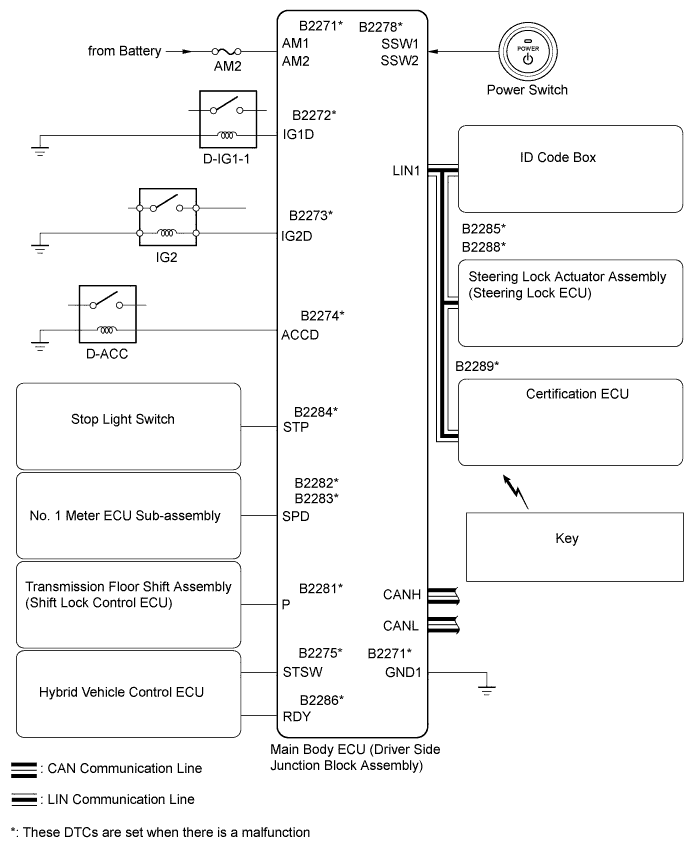
Symbols of main body ECU Signals SSW1/SSW2 Power switch ON (ACC, IG) signal IG1D D-IG1-1 relay operation signal ACCD D-ACC relay operation signal IG2D Ignition relay No. 2 (IG2) operation signal STP Stop light switch signal P Shift lock signal RDY Power switch ON (READY) signal STSW Hybrid control system activation request signal
-
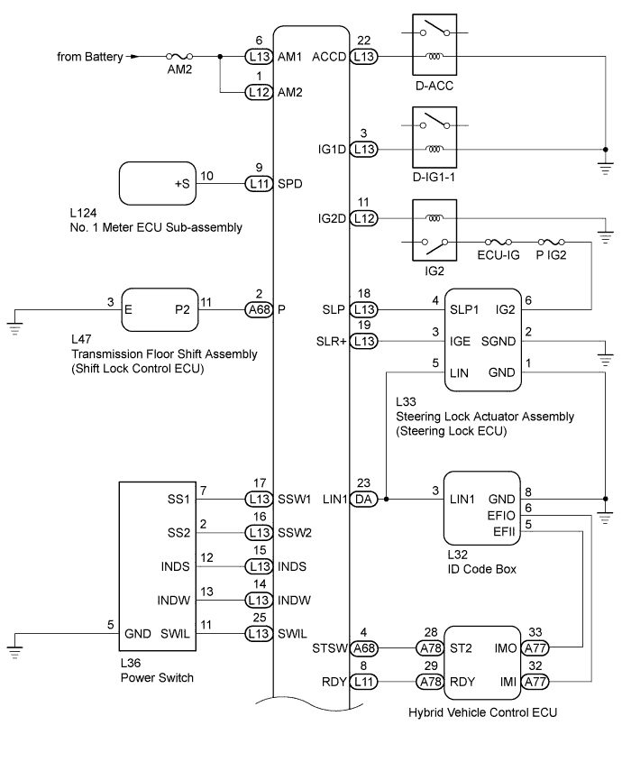
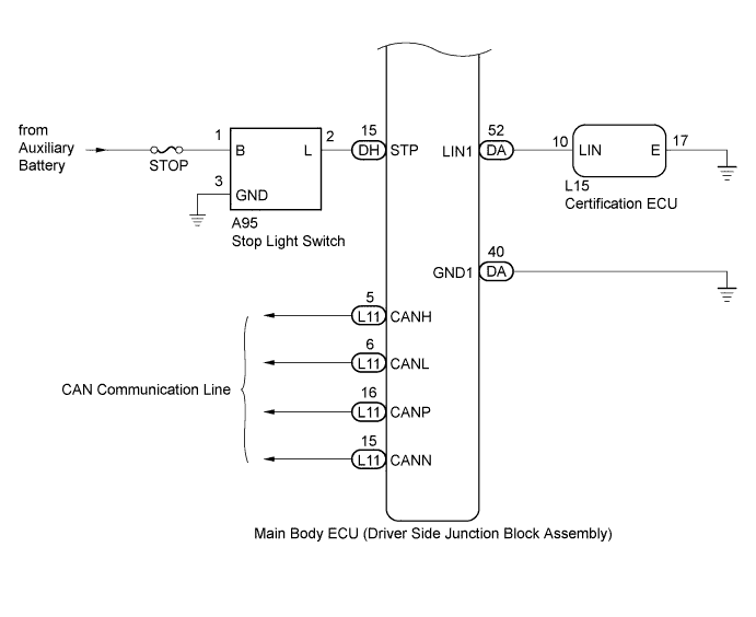
WIRING DIAGRAM
INSPECTION PROCEDURE
Note
Inspect the fuses of circuits related to this system before performing the following inspection procedure.
PROCEDURE
-
CHECK WHETHER POWER SWITCH IS ON (READY) AFTER STEERING LOCK INITIALIZATION
-
Move the shift lever to P.
-
Open and close the driver door when the power switch is OFF.
-
Check that pressing the power switch causes the power source mode to change to ON (READY).
Result Result Proceed to Power switch not ON (READY) A Power switch ON (READY) B Tech Tips
After the battery runs out, the hybrid control system may not turn ON (READY) if the steering lock ECU has not been initialized (lock / unlock may not be recorded) through the procedure described above.
B 
END (SYSTEM OK)
A 
-
-
CHECK WHETHER DTC OUTPUT RECURS
-
Clear the DTCs Click here.
-
Check whether the trouble recurs 5 seconds after the power switch is turned ON (IG).
-
Check whether DTCs for the main body ECU, certification ECU or hybrid vehicle control ECU are output.
Result Display (DTC output)
System name
Proceed to No DTC output A Main body ECU
ENTRY AND START SYSTEM
B Certification ECU
STEERING LOCK SYSTEM
C Certification ECU
ENGINE IMMOBILISER SYSTEM
D Hybrid vehicle control ECU
HYBRID CONTROL SYSTEM
E
B
GO TO ENTRY AND START SYSTEM (DIAGNOSTIC TROUBLE CODE CHART) Click here
C
GO TO STEERING LOCK SYSTEM (DIAGNOSTIC TROUBLE CODE CHART) Click here
D
GO TO ENGINE IMMOBILISER SYSTEM (DIAGNOSTIC TROUBLE CODE CHART) Click here
E
GO TO HYBRID CONTROL SYSTEM (DIAGNOSTIC TROUBLE CODE CHART) Click here
A
-
-
CHECK POWER SWITCH (SWITCH CONDITION)
-
Ensure the key is inside the cabin.
-
With the brake pedal released, check that the power source mode changes as shown below each time the power switch is pushed.
OK OFF → ON (ACC) → ON (IG) → OFF
NG
GO TO ENTRY AND START SYSTEM (POWER SOURCE MODE DOES NOT CHANGE) Click here
OK
-
-
READ VALUE USING INTELLIGENT TESTER (STEERING UNLOCK SWITCH)
-
Use the Data List to check if the steering lock condition is functioning properly.
Main Body Tester Display Measurement Item/Range Normal Condition Diagnostic Note Steering Unlock Switch Steering lock condition / ON or OFF ON: Steering is unlocked
OFF: Steering is locked
- OK ON (steering is unlocked) and OFF (steering is locked) are displayed on the tester.
NG
GO TO STEERING LOCK SYSTEM (STEERING LOCK MOTOR DRIVE POWER CIRCUIT) Click here
OK
-
-
READ VALUE USING INTELLIGENT TESTER (STOP LIGHT SW)
-
Use the Data List to check if the stop light switch is functioning properly.
Main Body Tester Display Measurement Item/Range Normal Condition Diagnostic Note Stop Light SW Stop Light switch/ON or OFF ON: Brake pedal is depressed
OFF: Brake pedal is released
- OK ON (brake pedal is depressed) and OFF (brake pedal is released) are displayed on the tester.
NG 
CHECK HARNESS AND CONNECTOR (MAIN BODY ECU - BATTERY, STOP LIGHT SWITCH ASSEMBLY) Click here
OK
-
-
READ VALUE USING INTELLIGENT TESTER (SHIFT P SIGNAL)
-
Use the Data List to check if the shift position is functioning properly.
Main Body Tester Display Measurement Item/Range Normal Condition Diagnostic Note Shift P Signal Shift P position signal/ON or OFF ON: Shift lever in P
OFF: Shift lever not in P
- OK ON (shift lever in P) and OFF (shift lever not in P) are displayed on the tester.
NG
INSPECT SHIFT LOCK CONTROL ECU Click here
OK
-
-
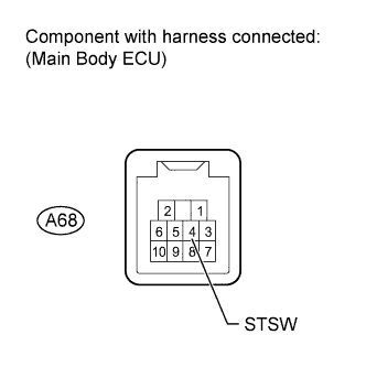
CHECK HARNESS AND CONNECTOR (MAIN BODY ECU - HYBRID VEHICLE CONTROL ECU)
-
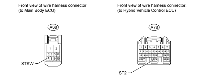
Disconnect the A68 main body ECU connector.
-
Disconnect the A78 hybrid vehicle control ECU connector.
-
Measure the resistance according to the value(s) in the table below.
Standard resistance Tester Connection Condition Specified Condition A68-4 (STSW) - A78-28 (ST2) Always Below 1 Ω A68-4 (STSW) or A78- 28 (ST2) - Body ground Always 10 kΩ or higher
NG
REPAIR OR REPLACE HARNESS OR CONNECTOR
OK
-
-
INSPECT MAIN BODY ECU
-
Measure the voltage according to the value(s) in the table below.
Tech Tips
The voltage is generated at terminal STSW for 0.3 seconds when the power switch is turned ON (READY).
Standard voltage Tester Connection Condition Specified Condition A68-4 (STSW) - Body ground Brake pedal depressed with shift lever in P, power switch pushed once 11 to 14 V
NG
REPLACE MAIN BODY ECU
OK
-
-
READ VALUE USING INTELLIGENT TESTER (L CODE CHECK)
-
Use the Data List to check if the L code certification result is functioning properly.
Main Body Tester Display Measurement Item/Range Normal Condition Diagnostic Note L Code Check L code certification result/NG or OK OK: L code certification result is normal
NG: L code certification result is abnormal
- OK OK is displayed on the tester.
NG
ECU CODE REGISTRATION Click here
OK
-
-
READ VALUE USING INTELLIGENT TESTER (S CODE CHECK)
-
Use the Data List to check if the S code certification result is functioning properly.
Main Body Tester Display Measurement Item/Range Normal Condition Diagnostic Note S Code Check S code certification result/NG or OK OK: S code certification result is normal
NG: S code certification result is abnormal
- OK OK is displayed on the tester.
NG
READ VALUE USING INTELLIGENT TESTER (S CODE CHECK) Click here
OK
-
-
READ VALUE USING INTELLIGENT TESTER (READY SIGNAL)
-
Use the Data List to check if the hybrid control system start request signal is functioning properly.
Entry&Start Tester Display Measurement Item/Range Normal Condition Diagnostic Note Ready Signal Hybrid control system start request signal monitor/ON or OFF ON: System is ON (READY)
OFF: System is OFF
- OK ON (system is ON (READY)) and OFF (system is OFF) are displayed on the tester.
NG
REPLACE CERTIFICATION ECU Click here
OK
-
-
REPLACE ID CODE BOX
-
Replace the ID code box.
-
Check that pressing the power switch causes the power source mode to change to ON (READY).
OK Power switch changes to ON (READY).
NG
REPLACE HYBRID VEHICLE CONTROL ECU Click here
OK 
END (SYSTEM OK)
-
-
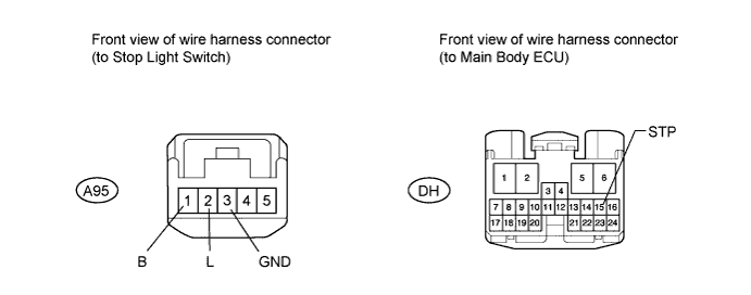
CHECK HARNESS AND CONNECTOR (MAIN BODY ECU - BATTERY, STOP LIGHT SWITCH ASSEMBLY)
-
Disconnect the DH main body ECU connector.
-
Disconnect the A95 stop light switch connector.
-
Measure the voltage and resistance according to the value(s) in the table below.
Standard voltage Tester Connection Condition Specified Condition A95-1 (B) - Body ground Always 11 to 14 V Standard resistance Tester Connection Condition Specified Condition DH-15 (STP) - A95-2 (L) Always Below 1 Ω DH-15 (STP) or A95-2 (L)- Body ground Always 10 kΩ or higher A95-3 (GND)- Body ground Always Below 1 Ω
NG
REPAIR OR REPLACE HARNESS OR CONNECTOR
OK
-
-
INSPECT STOP LIGHT SWITCH ASSEMBLY
-
Inspect the stop light switch assembly Click here.
Result Result Proceed to OK A NG (for LHD) B NG (for RHD) C
B
REPLACE STOP LIGHT SWITCH ASSEMBLY Click here
C
REPLACE STOP LIGHT SWITCH ASSEMBLY Click here
A
REPLACE MAIN BODY ECU
-
-
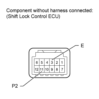
INSPECT SHIFT LOCK CONTROL ECU
-
Disconnect the L47 shift lock control ECU connector.
-
Measure the resistance according to the value(s) in the table below.
Standard resistance Tester Connection Condition Specified Condition 11 (P2) - 3 (E) Shift lever not in P Below 1 Ω 11 (P2) - 3 (E) Shift lever in P 10 kΩ or higher
NG
REPLACE TRANSMISSION FLOOR SHIFT ASSEMBLY (SHIFT LOCK CONTROL ECU) Click here
OK
-
-
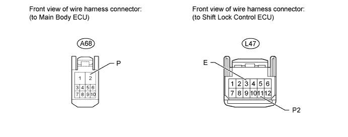
CHECK HARNESS AND CONNECTOR (MAIN BODY ECU - SHIFT LOCK CONTROL ECU, BODY GROUND)
-
Disconnect the A68 main body ECU connector.
-
Disconnect the L47 shift lock control ECU connector.
-
Measure the resistance according to the value(s) in the table below.
Standard resistance Tester Connection Condition Specified Condition A68-2 (P) - L47-11 (P2) Always Below 1 Ω L47-3 (E) - Body ground Always Below 1 Ω A68-2 (P) or L47-11 (P2) - Body ground Always 10 kΩ or higher
NG
REPAIR OR REPLACE HARNESS OR CONNECTOR
OK
REPLACE MAIN BODY ECU
-
-
ECU CODE REGISTRATION
-
Reregister the recognition codes in ECUs.
NEXT
-
-
READ VALUE USING INTELLIGENT TESTER (L CODE CHECK)
-
Use the Data List to check if the L code certification result is functioning properly again.
Main Body Tester Display Measurement Item/Range Normal Condition Diagnostic Note L Code Check L code certification result/NG or OK OK: L code certification result is normal
NG: L code certification result is abnormal
- OK OK is displayed on the tester.
NG
REPLACE STEERING LOCK ACTUATOR ASSEMBLY (STEERING LOCK ECU) Click here
OK
END (SYSTEM OK)
-
-
REPLACE STEERING LOCK ACTUATOR ASSEMBLY (STEERING LOCK ECU)
-
Replace the steering lock actuator assembly (steering lock ECU) Click here.
-
Check that pressing the power switch causes the power source mode to change to ON (READY).
OK Power switch ON (READY).
NG
REPLACE ID CODE BOX
OK
END (SYSTEM OK)
-
-
READ VALUE USING INTELLIGENT TESTER (S CODE CHECK)
-
When another electrical key control transmitter is used, use the Data List to check again if the S code certification result is functioning properly.
Main Body Tester Display Measurement Item/Range Normal Condition Diagnostic Note S Code Check S code certification result/NG or OK OK: S code certification result is normal
NG: S code certification result is abnormal
- OK OK is displayed on the tester.
NG
REPLACE CERTIFICATION ECU Click here
OK
END (DOOR CONTROL TRANSMITTER IS DEFECTIVE)
-
-
REPLACE CERTIFICATION ECU
-
Replace the certification ECU.
-
Check that pressing the power switch causes the power source mode to change to ON (READY).
OK Power switch ON (READY).
NG
REPLACE ID CODE BOX
OK
END (SYSTEM OK)
-