ENTRY AND START SYSTEM, Diagnostic DTC:B2284

| DTC Code | DTC Name |
|---|---|
| B2284 | Brake Signal Malfunction |
DESCRIPTION
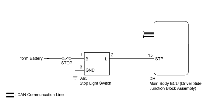
This DTC is output when: 1) the brake signal circuit between the main body ECU and the stop light switch is malfunctioning; and 2) the CAN information is inconsistent.
| DTC No. | Detection Condition | Trouble Area |
|---|---|---|
| B2284 | Communication or communication line is abnormal between main body ECU and stop light switch |
|
WIRING DIAGRAM
INSPECTION PROCEDURE
Note
Inspect the fuses of circuits related to this system before performing the following inspection procedure.
PROCEDURE
-
READ VALUE USING INTELLIGENT TESTER (STOP LIGHT SW)
-
Use the Data List to check if the stop light switch is functioning properly.
Main Body Tester Display Measurement Item/Range Normal Condition Diagnostic Note Stop Light SW Stop light switch/ON or OFF ON: Brake pedal depressed
OFF: Brake pedal released
- Result Result Proceed to Display on tester does not change according to brake pedal operation A Display on tester changes according to brake pedal operation B
B 
REPLACE MAIN BODY ECU
A 
-
-
CHECK HARNESS AND CONNECTOR (MAIN BODY ECU - BATTERY, STOP LIGHT SWITCH ASSEMBLY)
-
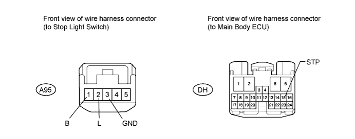
Disconnect the DH main body ECU connector.
-
Disconnect the A95 stop light switch connector.
-
Measure the voltage and resistance according to the value(s) in the table below.
Standard voltage Tester Connection Condition Specified Condition A95-1 (B) - Body ground Always 11 to 14 V Standard resistance Tester Connection Condition Specified Condition DH-15 (STP) - A95-2 (L) Always Below 1 Ω DH-15 (STP) or A95-2 (L)- Body ground Always 10 kΩ or higher A95-3 (GND)- Body ground Always Below 1 Ω
NG
REPAIR OR REPLACE HARNESS OR CONNECTOR
OK
-
-
INSPECT STOP LIGHT SWITCH ASSEMBLY
-
Inspect the stop light switch assembly Click here.
Result Result Proceed to OK A NG (for LHD) B NG (for RHD) C
B
REPLACE STOP LIGHT SWITCH ASSEMBLY Click here
C
REPLACE STOP LIGHT SWITCH ASSEMBLY Click here
A 
REPLACE MAIN BODY ECU
-