ENTRY AND START SYSTEM, Diagnostic DTC:B2278

| DTC Code | DTC Name |
|---|---|
| B2278 | Power Switch Circuit Malfunction |
DESCRIPTION
This DTC is output when: 1) a malfunction is detected between the main body ECU and the power switch; or 2) either of the switches inside the power switch is malfunctioning.
| DTC Code | Detection Condition | Trouble Area |
|---|---|---|
| B2278 | Communication is abnormal between main body ECU and power switch or power switch is defective |
|
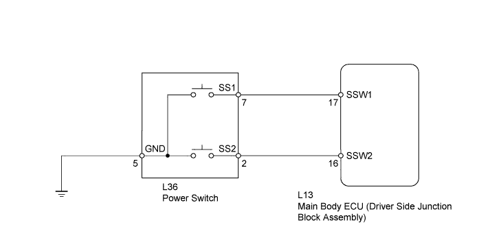
WIRING DIAGRAM
INSPECTION PROCEDURE
PROCEDURE
-
READ VALUE USING INTELLIGENT TESTER (START SWITCH 1, 2)
-
Use the Data List to check if the power switch is functioning properly.
Main Body Tester Display Measurement Item/Range Normal Condition Diagnostic Note Start Switch 1 Start Switch 1/ON or OFF ON: Power switch ON (IG)
OFF: Power switch OFF
- Start Switch 2 Start Switch 2/ON or OFF ON: Power switch ON (IG)
OFF: Power switch OFF
- OK When the power switch is turned ON (IG), ON is displayed on the tester.
NG 
INSPECT POWER SWITCH Click here
OK 
-
-
CHECK POWER SWITCH (SWITCH CONDITION)
-
Ensure the key is inside the cabin.
-
With the brake pedal released, check that the power source mode changes as shown below each time the power switch is pushed.
OK OFF → ON (ACC) → ON (IG) → OFF
NG 
GO TO ENTRY AND START SYSTEM (POWER SOURCE MODE DOES NOT CHANGE) Click here
OK 
USE SIMULATION METHOD TO CHECK Click here
-
-
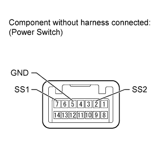
INSPECT POWER SWITCH
-
Disconnect the L36 power switch connector.
-
Measure the resistance according to the value(s) in the table below.
Standard resistance Tester Connection Switch Condition Specified Condition 7 (SS1) - 5 (GND) Pushed Below 1 Ω 2 (SS2) - 5 (GND) Pushed Below 1 Ω 7 (SS1) - 5 (GND) Not pushed 10 kΩ or higher 2 (SS2) - 5 (GND) Not pushed 10 kΩ or higher
NG
REPLACE POWER SWITCH Click here
OK
-
-
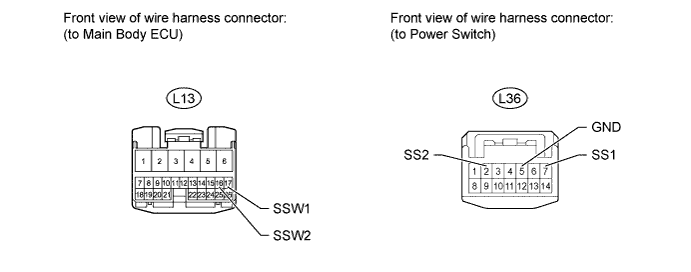
CHECK HARNESS AND CONNECTOR (MAIN BODY ECU - POWER SWITCH, BODY GROUND)
-
Disconnect the L13 main body ECU connector.
-
Disconnect the L36 power switch connector.
-
Measure the resistance according to the value(s) in the table below.
Standard resistance Tester Connection Condition Specified Condition L13-17 (SSW1) - L36-7 (SS1) Always Below 1 Ω L13-16 (SSW2) - L36-2 (SS2) Always Below 1 Ω L36-5 (GND) - Body ground Always Below 1 Ω L13-17 (SSW1) or L36-7 (SS1) - Body ground Always 10 kΩ or higher L13-16 (SSW2) or L36-2 (SS2) - Body ground Always 10 kΩ or higher
NG
REPAIR OR REPLACE HARNESS OR CONNECTOR
OK
REPLACE MAIN BODY ECU
-