OIL PUMP INSTALLATION

Tech Tips
When viewed from the rear of the engine assembly, Bank 1 is on the left side and Bank 2 is on the right side.
-
INSTALL WATER INLET PIPE
-
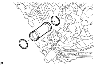
Apply soapy water to 2 new O-rings and install them to the inlet pipe.
-
Install the inlet pipe to the No. 1 heat exchanger cover.
-
-
INSTALL TIMING CHAIN COVER SUB-ASSEMBLY
-
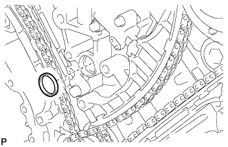
Install a new oil pump gasket.
-
Install a new O-ring.
-
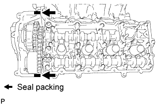
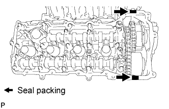
Apply seal packing in a continuous line to the timing chain cover as shown in the following illustration.
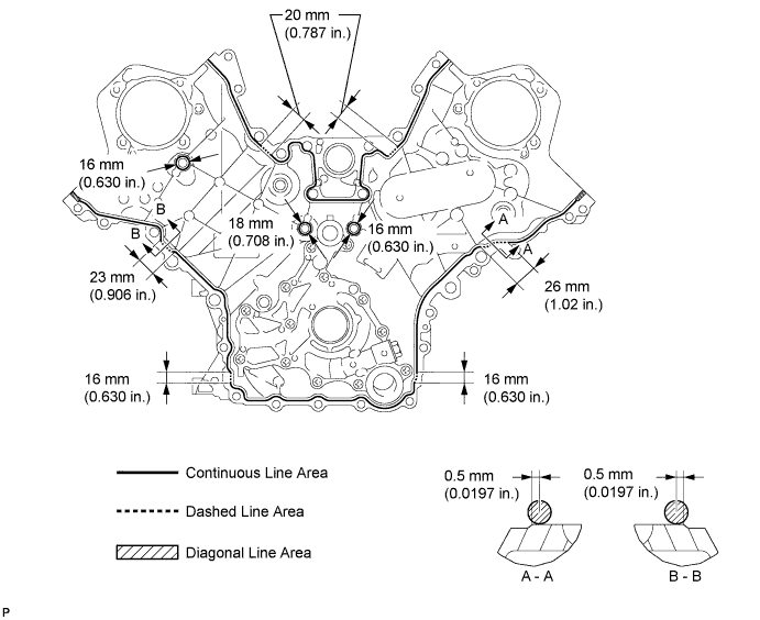
Seal packing Toyota Genuine Seal Packing Black, Three Bond 1207B or equivalent
-
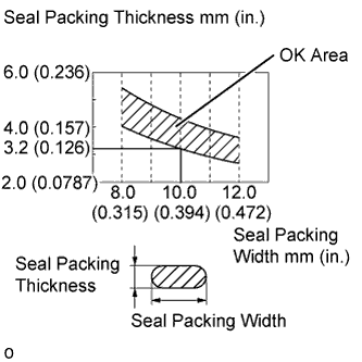
Apply Seal Packing as Follows Area Seal Packing Diameter Application position from inside edge of cover Continuous Line Area 3.0 to 4.0 mm (0.118 to 0.157 in.) 2.5 mm (0.0984 in.) Dashed Line Area 6.4 mm (0.252 in.) or more, or within OK area shown in illustration 0.5 mm (0.0197 in.) Diagonal Line Area 3.0 to 4.0 mm (0.118 to 0.157 in.) 5.5 mm (0.217 in.)
Note
-
When the contact surfaces are wet, wipe them with an oil-free cloth before applying seal packing.
-
Install the chain cover within 3 minutes and tighten the bolts within 10 minutes after applying seal packing.
-
Do not start the engine for at least 2 hours after installation.
-
-
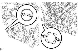
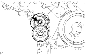
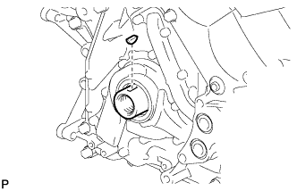
Align the drive rotor spline of the oil pump and the crankshaft as shown in the illustration. Install the spline and chain cover to the crankshaft.
-
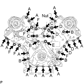
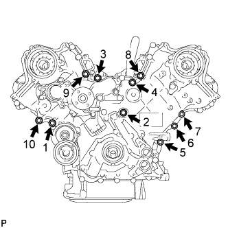
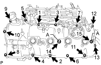
Temporarily install the timing chain cover with the 30 bolts and nut.
Bolt Length Item Length Thread Diameter Bolt A 25 mm (0.984 in.) 8 mm (0.315 in.) Bolt B 55 mm (2.17 in.) 8 mm (0.315 in.) Bolt C 70 mm (2.76 in.) 8 mm (0.315 in.) Bolt D 35 mm (1.38 in.) 10 mm (0.394 in.) Bolt E 55 mm (2.17 in.) 10 mm (0.394 in.) Bolt F 80 mm (3.15 in.) 10 mm (0.394 in.) Note
Make sure that there is no oil on the bolt threads.
-
Tighten the bolt.
- Torque:
- 23 N*m { 235 kgf*cm, 17 ft.*lbf }
-
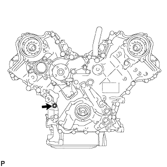
Install the belt tensioner with the bolt.
- Torque:
- 23 N*m { 235 kgf*cm, 17 ft.*lbf }
-
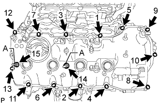
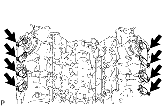
Tighten the 10 bolts in several steps, in the sequence shown in the illustration.
- Torque:
- 47 N*m { 479 kgf*cm, 35 ft.*lbf }
-
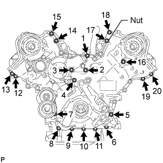
Tighten the 19 bolts and nut in several steps, in the sequence shown in the illustration.
- Torque:
- 23 N*m { 235 kgf*cm, 17 ft.*lbf }
Note
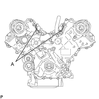
After the installation, if the seal packing has seeped out at the areas labeled A shown in the illustration, wipe it off.
-
Install 2 new gaskets and the 2 plugs.
- Torque:
- 46 N*m { 469 kgf*cm, 34 ft.*lbf }
-
-
INSTALL CYLINDER HEAD COVER SUB-ASSEMBLY LH
-
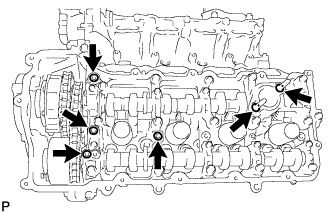
Install 4 new gaskets and 2 new O-rings to the camshaft bearing caps (No. 2, No. 3 and No. 7).
-
Install a new gasket to the cylinder head cover.
Note
Remove any oil from the contact surface.
-
Apply seal packing as shown the illustration.
Seal packing Toyota Genuine Seal Packing Black, Three Bond 1207B or equivalent Standard seal diameter 2.0 to 3.0 mm (0.0787 to 0.118 in.) Note
-
Remove any oil from the contact surface.
-
Install the cylinder head cover within 3 minutes and tighten the bolts within 15 minutes after applying seal packing.
-
Do not start the engine for at least 2 hours after the installation.
-
-
Install the cylinder head cover and 2 new seal washers with the 15 bolts in the order shown in the illustration.
- Torque:
- for bolt A
- 21 N*m { 214 kgf*cm, 15 ft.*lbf }
- except bolt A
- 12 N*m { 122 kgf*cm, 9 ft.*lbf }
-
Install the fuel pump spacer.
-
-
INSTALL CYLINDER HEAD COVER SUB-ASSEMBLY RH
-
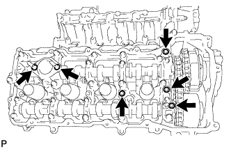
Install 4 new gaskets and 2 new O-rings to the camshaft bearing caps (No. 1, No. 3 and No. 6).
-
Install a new gasket to the cylinder head cover.
Note
Remove any oil from the contact surface.
-
Apply seal packing as shown the illustration.
Seal packing Toyota Genuine Seal Packing Black, Three Bond 1207B or equivalent Standard seal diameter 2.0 to 3.0 mm (0.0787 to 0.118 in.) Note
-
Remove any oil from the contact surface.
-
Install the cylinder head cover within 3 minutes and tighten the bolts within 15 minutes after applying seal packing.
-
Do not start the engine for at least 2 hours after the installation.
-
-
Install the cylinder head cover and 2 new seal washers with the 15 bolts in the order shown in the illustration.
- Torque:
- for bolt A
- 21 N*m { 214 kgf*cm, 15 ft.*lbf }
- except bolt A
- 12 N*m { 122 kgf*cm, 9 ft.*lbf }
-
Install the fuel pump spacer.
-
-
INSTALL FRONT CRANKSHAFT OIL SEAL
-
Apply MP grease to the lip of a new oil seal.
-
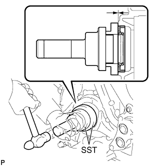
Using SST and a hammer, tap in the oil seal to a depth between 0 to 1.0 mm (0 to 0.0394 in.) from the timing chain cover edge.
- SST
- 09223-22010
- 09506-35010
Note
-
Keep the lip free from foreign matter.
-
Do not tap the oil seal at an angle.
-
-
INSTALL CRANKSHAFT TIMING GEAR KEY
-
Install the crankshaft timing gear key to the crankshaft.
-
-
INSTALL IGNITION COIL ASSEMBLY
-
Install the 8 ignition coils with the 8 bolts.
- Torque:
- 10 N*m { 102 kgf*cm, 7 ft.*lbf }
-
-
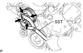
INSTALL CRANKSHAFT PULLEY
-
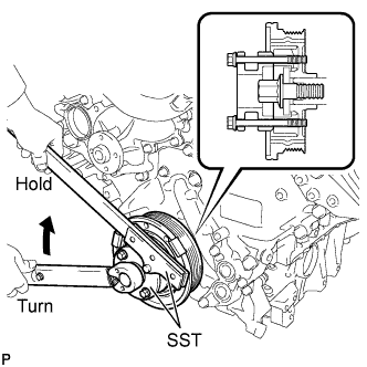
Align the pulley set key with the key groove of the pulley, and slide on the pulley.
-
Using SST, install the pulley bolt.
- SST
- 09213-54015 ( 90119-08216 )
- 09330-00021
- Torque:
- 300 N*m { 3059 kgf*cm, 221 ft.*lbf }
-
-
INSTALL OIL FILTER BRACKET
-
Install 2 new gaskets and the filter bracket with the 3 bolts.
- Torque:
- 21 N*m { 214 kgf*cm, 15 ft.*lbf }
-
-
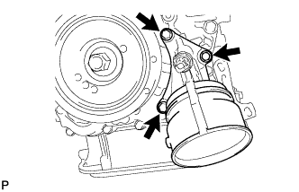
INSTALL OIL FILTER ELEMENT
-
Clean the inside of the oil filter cap, its threads and O-ring groove.
-
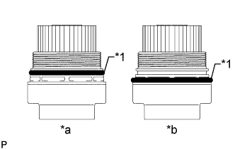
Text in Illustration *1 O-Ring *a CORRECT *b INCORRECT Apply a small amount of engine oil to a new O-ring and install it to the oil filter cap.
Note
-
Be sure to install the O-ring in the proper location, otherwise oil may leak.
-
Do not twist the O-ring.
-
-
Set a new oil filter element to the oil filter cap.
-
Remove any dirt or foreign matter from the installation surface of the engine.
-
Apply a small amount of engine oil to the O-ring again and temporarily install the oil filter cap.
-
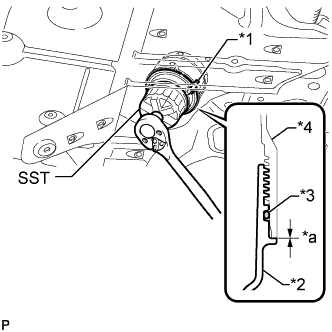
Text in Illustration *1 Oil Filter Bracket Clip *2 Oil Filter Cap *3 O-Ring *4 Oil Filter Bracket *a No Clearance Using SST, tighten the oil filter cap.
- SST
- 09228-06501
- Torque:
- 25 N*m { 255 kgf*cm, 18 ft.*lbf }
Note
-
Do not remove the oil filter bracket clip.
-
Make sure that the oil filter is installed securely as shown in the illustration.
-
Be careful that the O-ring does not get caught between any surrounding parts.
-
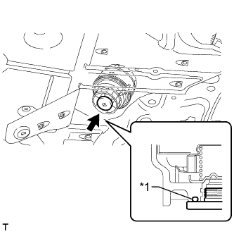
Text in Illustration *1 O-Ring Apply a small amount of engine oil to a new drain plug O-ring, and install it to the oil filter cap.
Note
Before installing the O-ring, remove any dirt or foreign matter from the installation surface of the oil filter cap.
-
Install the oil filter drain plug.
- Torque:
- 13 N*m { 133 kgf*cm, 10 ft.*lbf }
Note
Be careful that the O-ring does not get caught between any surrounding parts.
-
-
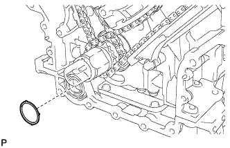
INSTALL CAMSHAFT TIMING CONTROL MOTOR ASSEMBLY RH
-
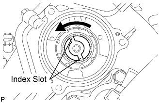
Turn the camshaft timing gear assembly's intermediate shaft index slot in the counterclockwise direction by hand, and set it to the maximum retard angle position.
Tech Tips
-
When the cam of the camshaft lifts the valve, the intermediate shaft becomes difficult to turn.
-
The position where the intermediate shaft stops is the maximum retard angle.
-
-
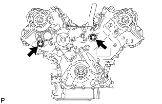
Install a new O-ring to the timing chain cover.
-
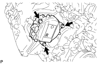
Align the joint of the camshaft timing control motor and the keyway of the camshaft timing gear assembly, and install the motor with the 3 bolts.
- Torque:
- 21 N*m { 214 kgf*cm, 15 ft.*lbf }
Note
-
Check that [R] is printed on the label of the camshaft timing control motor.
-
Do not allow foreign matter to contact the oil seal face of the camshaft timing control motor (connecting surface with timing chain cover sub-assembly).
-
When installing the camshaft timing control motor, do not use excessive force.
-
Align the timing chain cover sub-assembly knock pin with the camshaft timing control motor pin hole to install the camshaft timing control motor.
-
Install the camshaft timing control motor with the arrow facing upward, as shown in the illustration.
-
Do not drop the camshaft timing control motor. If dropped, replace it.
-
Do not disassemble the camshaft timing control motor assembly. If disassembled, replace it.
-
-
INSTALL CAMSHAFT TIMING CONTROL MOTOR ASSEMBLY LH
-
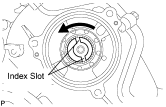
Turn the camshaft timing gear assembly's intermediate shaft index slot in the counterclockwise direction by hand, and set it to the maximum retard angle position.
Tech Tips
-
When the cam of the camshaft lifts the valve, the intermediate shaft becomes difficult to turn.
-
The position where the intermediate shaft stops is the maximum retard angle.
-
-
Install a new O-ring to the timing chain cover.
-
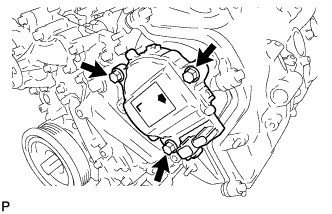
Align the joint of the camshaft timing control motor and the keyway of the camshaft timing gear assembly, and install the motor with the 3 bolts.
- Torque:
- 21 N*m { 214 kgf*cm, 15 ft.*lbf }
Note
-
Check that [L] is printed on the label of the camshaft timing control motor.
-
Do not allow foreign matter to contact the oil seal face of the camshaft timing control motor (connecting surface with timing chain cover sub-assembly).
-
When installing the camshaft timing control motor, do not use excessive force.
-
Align the timing chain cover sub-assembly knock pin with the camshaft timing control motor pin hole to install the camshaft timing control motor.
-
Install the camshaft timing control motor with the arrow facing upward, as shown in the illustration.
-
Do not drop the camshaft timing control motor. If dropped, replace it.
-
Do not disassemble the camshaft timing control motor assembly. If disassembled, replace it.
-
-
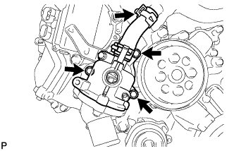
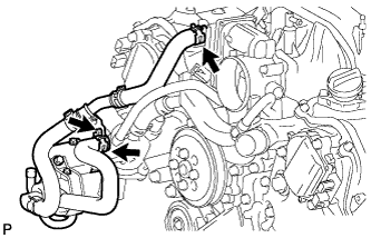
INSTALL FRONT WATER BY-PASS JOINT
-
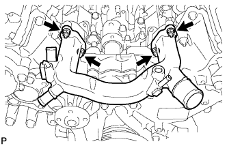
Install the 2 new gaskets and water by-pass joint with the 4 nuts.
- Torque:
- 21 N*m { 214 kgf*cm, 15 ft.*lbf }
-
-
INSTALL WATER PUMP PULLEY
-
Temporarily install the pulley with the 4 bolts.
-
Using SST, hold the pulley and tighten the 4 bolts.
- SST
- 09960-10010 ( 09962-01000, 09963-01000 )
- Torque:
- 21 N*m { 214 kgf*cm, 15 ft.*lbf }
-
-
INSTALL WATER INLET HOUSING
-
Install a new gasket and the inlet housing with the 3 bolts.
- Torque:
- 21 N*m { 214 kgf*cm, 15 ft.*lbf }
-
Using needle-nose pliers, grip the claws of the clip and slide the clip to connect the water inlet hose.
-
-
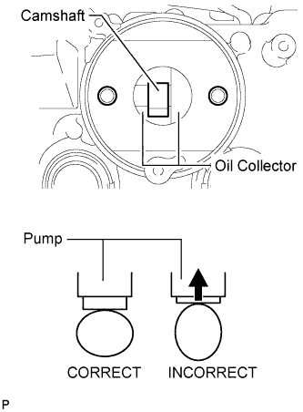
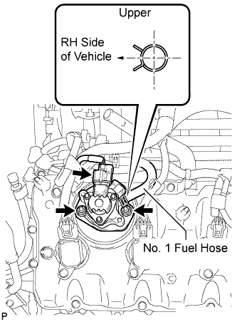
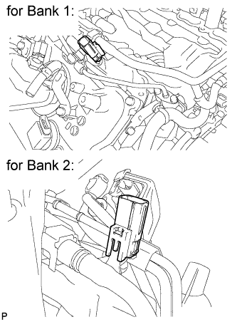
INSTALL FUEL PUMP ASSEMBLY (for Bank 2)
-
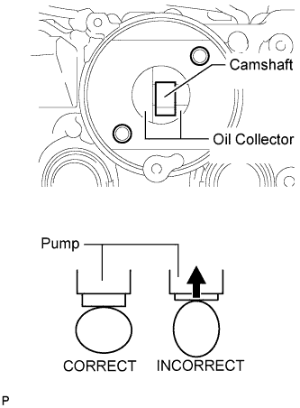
Turn the camshaft until the flat of the cam is facing the cylinder head cover's fuel pump attachment hole, as shown in the illustration.
Tech Tips
By not using the camshaft lobe to push up the pump lifter surface, it is easier to install the fuel pump and No. 2 fuel pipe later.
-
Pour 30 cc (1.8 cu. in.) of engine oil through the cylinder head cover's fuel pump attachment hole into the cylinder head oil collector.
-
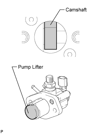
Apply a coat of engine oil to the pump activation cam and pump lifter.
-
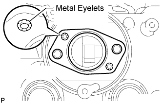
Install a new fuel pump insulator to the cylinder head cover. Then pass the 2 stud bolts through the holes of the fuel pump and set it on the insulator.
Note
Install the insulator so that the open sides of the metal eyelets are facing outward, as shown in the illustration.
-
Install the fuel pump with the 2 nuts.
- Torque:
- 25 N*m { 255 kgf*cm, 18 ft.*lbf }
-
Connect the No. 1 fuel hose.
Tech Tips
As shown in the illustration.
-
Connect the fuel pump connector.
-
-
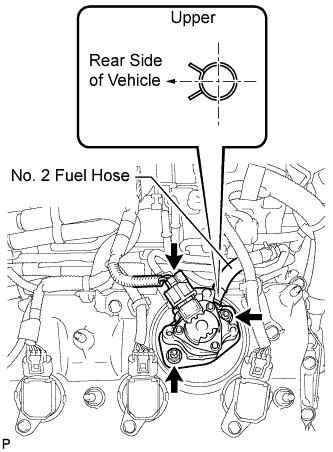
INSTALL FUEL PUMP ASSEMBLY (for Bank 1)
-
Turn the camshaft until the flat of the cam is facing the cylinder head cover's fuel pump attachment hole, as shown in the illustration.
Tech Tips
By not using the camshaft lobe to push up the pump lifter surface, it is easier to install the fuel pump and No. 3 fuel pipe later.
-
Pour 30 cc (1.8 cu. in.) of engine oil through the cylinder head cover's fuel pump attachment hole into the cylinder head oil collector.
-
Apply a coat of engine oil to the pump activation cam and pump lifter.
-
Install a new fuel pump insulator to the cylinder head cover. Then pass the 2 stud bolts through the holes of the fuel pump and set it on the insulator.
Note
Install the insulator so that the open sides of the metal eyelets are facing outward, as shown in the illustration.
-
Install the fuel pump with the 2 nuts.
- Torque:
- 25 N*m { 255 kgf*cm, 18 ft.*lbf }
-
Connect the No. 2 fuel hose.
Tech Tips
As shown in the illustration.
-
Connect the fuel pump connector.
-
-
INSTALL NO. 3 FUEL PIPE SUB-ASSEMBLY
-
Install a new O-ring, new No. 1 backup ring, new No. 2 backup ring and a new E-ring to the No. 3 fuel pipe sub-assembly as shown in the illustration.
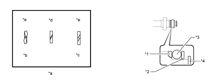
Text in Illustration *1 No. 1 Backup Ring *2 No. 2 Backup Ring *3 O-Ring *4 E-Ring *a Alignment Opening *b Overlapped *c Stretched *d CORRECT *e INCORRECT - - Note
-
Check that there is no foreign matter or damaged areas in the No. 3 fuel pipe sub-assembly O-ring groove.
-
Check that the No. 1 backup ring and No. 2 backup ring are installed in the correct direction.
-
Make sure that the backup rings and O-ring are installed in the correct order.
-
Check that the alignment openings of the backup rings are not overlapped or stretched as shown in the illustration.
-
After installing the O-ring, check that it is not contaminated with foreign matter and is not damaged.
-
-
Apply engine oil to the O-ring.
Note
Make sure there is no gasoline on the O-ring and inside the installation hole.
-
Temporarily install the No. 3 fuel pipe sub-assembly to the delivery pipe with the 2 bolts.
-
Temporarily install the No. 3 fuel pipe sub-assembly to the fuel pump.
Note
Be careful not to damage the sealing surface of the No. 3 fuel pipe sub-assembly when temporarily installing the No. 3 fuel pipe sub-assembly.
-
Tighten the 2 bolts in several passes.
- Torque:
- 10 N*m { 102 kgf*cm, 7 ft.*lbf }
-
Text in Illustration *1 Union Nut Wrench Using a 19 mm union nut wrench, tighten the union nut.
- Torque:
- 30 N*m { 306 kgf*cm, 22 ft.*lbf }
Note
-
There must be absolutely no free play in the union on the fuel pump side. If the union on the fuel pump side has free play, replace the fuel pump.
-
Use the formula to calculate special torque values for situations where a union nut wrench is combined with a torque wrench Click here.
Tech Tips
Make sure use the union nut wrench and torque wrench are connected in a straight line.
-
Connect the fuel pump connector.
-
-
INSTALL NO. 2 FUEL PIPE SUB-ASSEMBLY
Tech Tips
The installation procedures are the same as for the No. 3 fuel pipe sub-assembly.
-
INSTALL FUEL PRESSURE PULSATION DAMPER ASSEMBLY
-
Apply a light coat of engine oil to the threads and gasket seating surfaces of the 2 fuel pressure pulsation damper assemblies.
-
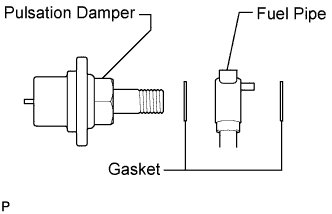
Temporarily install each dampers together with 2 new gaskets and the fuel pipe to the fuel pump.
-
Install the 2 clamp bolts.
- Torque:
- 10 N*m { 102 kgf*cm, 7 ft.*lbf }
-
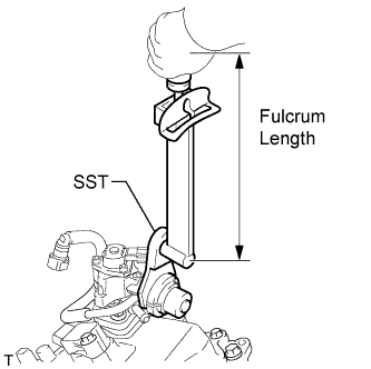
Using SST, tighten the 2 dampers.
- SST
- 09612-24014 ( 09617-24011 )
- Torque:
- without SST
- 36 N*m { 367 kgf*cm, 27 ft.*lbf }
- with SST
- 31 N*m { 313 kgf*cm, 23 ft.*lbf }
Tech Tips
-
Use a torque wrench with a fulcrum length of 300 mm (11.8 in.). When using a torque wrench with a fulcrum length that is not 300 mm (11.8 in.), calculate the torque specification for the torque wrench and SST based on the "without SST" torque specification Click here.
-
Make sure SST and the torque wrench are connected in a straight line.
-
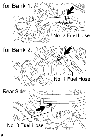
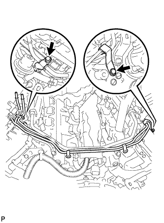
Connect the 3 fuel hoses.
-
Connect the 2 delivery pipe connectors to the delivery pipe.
-
-
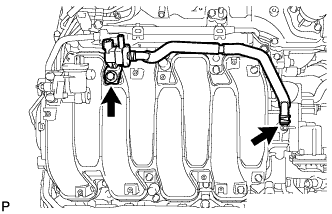
INSTALL INTAKE MANIFOLD ASSEMBLY
-
Install 2 new gaskets to the intake manifold.
-
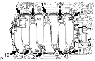
Temporarily install the intake manifold with the 2 nuts and 8 bolts. Then tighten the 2 nuts and 8 bolts uniformly in the order shown in the illustration.
- Torque:
- 21 N*m { 214 kgf*cm, 15 ft.*lbf }
-
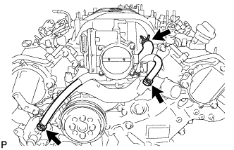
Connect the No. 1 ventilation hose and 2 water by-pass hoses as shown in the illustration.
-
-
INSTALL WATER BY-PASS PIPE SUB-ASSEMBLY
-
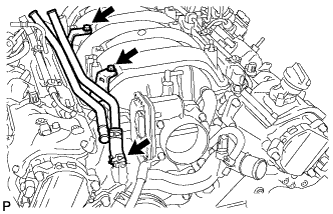
Slide the clamp to connect the water inlet hose to the front water by-pass joint.
-
Install the water by-pass pipe with the 2 bolts.
- Torque:
- 10 N*m { 102 kgf*cm, 7 ft.*lbf }
-
-
INSTALL HEATER WATER PUMP ASSEMBLY
-
Install the heater water pump with the bolt.
- Torque:
- 10 N*m { 102 kgf*cm, 7 ft.*lbf }
-
Slide the 2 clamps to connect the 2 hoses to the water by-pass pipe and water inlet housing.
-
-
INSTALL PURGE VSV
-
Install the purge VSV with the bolt.
- Torque:
- 21 N*m { 214 kgf*cm, 15 ft.*lbf }
-
Connect the purge line hose to the intake manifold.
-
-
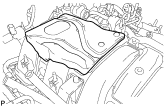
INSTALL NO. 1 ENGINE COVER
-
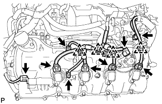
INSTALL INJECTOR DRIVER
Note
-
Be careful not to drop or strike the injector driver.
-
The injector driver is grounded at the bolt and nut. To ensure that it is grounded, clean all oil and foreign matter from the installation areas of the injector driver and engine before installing the injector driver.
-
Temporarily install the 2 injector drivers with the 2 bolts and 2 nuts.
-
Tighten the 2 bolts and 2 nuts in the order shown in the illustration.
- Torque:
- 10 N*m { 102 kgf*cm, 7 ft.*lbf }
-
-
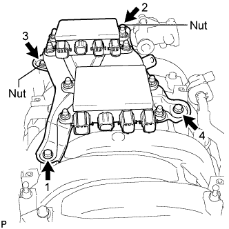
INSTALL ENGINE WIRE
-
Engine Upper Side:
-
Connect the engine wire with the 4 nuts.
- Torque:
- 10 N*m { 102 kgf*cm, 7 ft.*lbf }
-
Install the 2 clamp brackets with the 2 bolts and connect the 2 clamps.
- Torque:
- 10 N*m { 102 kgf*cm, 7 ft.*lbf }
-
Connect the intake air control valve actuator connector.
-
Connect the purge VSV connector.
-
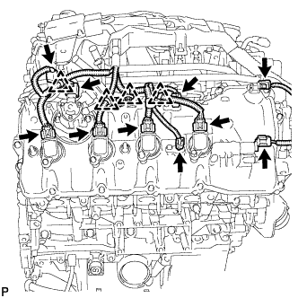
Connect the 2 clamps.
-
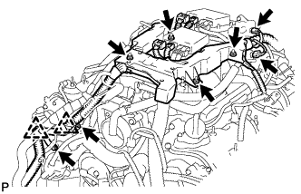
Connect the 8 injector driver connectors as shown in the illustration.
-
-
Engine Rear Side:
-
Connect the 2 ground wires with the 2 bolts.
- Torque:
- 10 N*m { 102 kgf*cm, 7 ft.*lbf }
-
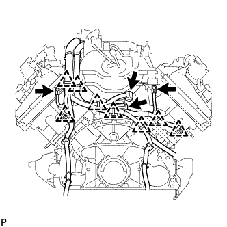
Connect the 8 clamps.
-
Connect the fuel relief valve connector.
-
Connect the engine wire connector.
-
-
Engine RH Side:
-
Connect the 4 clamps.
-
Connect the fuel injector connector.
-
Connect the camshaft position sensor connector.
-
Connect the engine wire connector.
-
Connect the fuel pump connector (for high pressure).
-
Connect the 2 VVT sensor connectors.
-
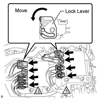
Connect the 4 ignition coil connectors.
-
Connect the camshaft timing control valve connector.
-
-
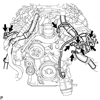
Engine Front Side:
-
Connect the 3 ground wires with the 3 bolts.
- Torque:
- 10 N*m { 102 kgf*cm, 7 ft.*lbf }
-
Connect the clamp.
-
Connect the 2 camshaft timing control motor connectors (for Bank 2).
-
Connect the 2 camshaft timing control motor connectors (for Bank 1).
-
Connect the engine coolant temperature sensor connector.
-
-
Engine LH Side:
-
Connect the 4 clamps.
-
Connect the fuel injector connector.
-
Connect the fuel pump connector (for high pressure).
-
Connect the 2 VVT sensor connectors.
-
Connect the 4 ignition coil connectors.
-
Connect the camshaft timing control valve connector.
-
-
-
INSTALL NO. 5 COVER SUB-ASSEMBLY
-
Install the No. 5 cover.
-
-
INSTALL ENGINE COVER SUB-ASSEMBLY RH
-
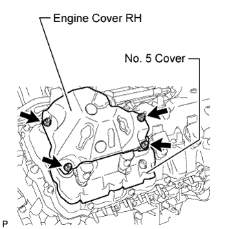
Install the engine cover RH with the 4 nuts.
- Torque:
- 21 N*m { 214 kgf*cm, 15 ft.*lbf }
-
-
INSTALL NO. 6 COVER SUB-ASSEMBLY
-
Install the No. 6 cover.
-
-
INSTALL ENGINE COVER SUB-ASSEMBLY LH
-
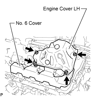
Install the engine cover LH with the 4 nuts.
- Torque:
- 21 N*m { 214 kgf*cm, 15 ft.*lbf }
-
-
INSTALL WITH MOTOR COMPRESSOR ASSEMBLY
-
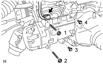
Using an E8 ''TORX'' socket wrench, install the with motor compressor assembly with the 2 stud bolts
- Torque:
- 10 N*m { 102 kgf*cm, 7 ft.*lbf }
-
Install the 2 bolts and 2 nuts.
- Torque:
- 25 N*m { 250 kgf*cm, 18 ft.*lbf }
Note
Tighten the nuts and bolts in the order shown in the illustration to install the cooler compressor.
-
Connect the connector.
-
-
INSTALL V-RIBBED BELT
-
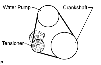
Install the V-ribbed belt as shown in the illustration.
Note
Check that the V-ribbed belt is properly set to each pulley.
-
Rotate the tensioner pulley counterclockwise, and then remove the bar.
-
-
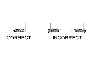
After installing the belt, check that it fits properly in the ribbed grooves.
-
Check by hand to confirm that the belt has not slipped out of the grooves on the bottom of the pulley.
-
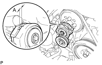
Check that the alignment mark on the belt tensioner is within area "A".
If it is outside area "A", replace the V-ribbed belt.
Tech Tips
When a new belt is installed, the alignment mark should be within area "B". If not, the V-ribbed belt is not installed correctly.
-
-
INSTALL ENGINE ASSEMBLY