OIL PUMP REMOVAL

Tech Tips
When viewed from the rear of the engine assembly, Bank 1 is on the left side and Bank 2 is on the right side.
-
REMOVE ENGINE ASSEMBLY
-
REMOVE V-RIBBED BELT
-
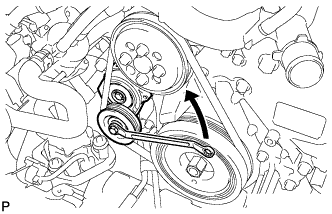
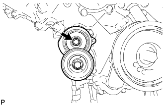
Rotate the tensioner pulley counterclockwise to loosen the V-ribbed belt tension assembly.
Tech Tips
The pulley bolt for the V-ribbed belt tensioner assembly has a left-handed thread.
-
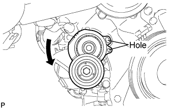
While turning the V-ribbed belt tensioner assembly counterclockwise, align the holes. Insert a bar with a diameter of 5 mm (0.197 in.) into the holes to fix the V-ribbed belt tensioner assembly in place.
-
Remove the V-ribbed belt.
-
-
REMOVE WITH MOTOR COMPRESSOR ASSEMBLY
-
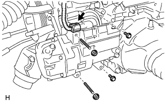
Disconnect the connector.
-
Remove the 2 bolts and 2 nuts.
-
Using an E8 ''TORX'' socket wrench, remove the 2 stud bolts and with motor compressor assembly.
-
-
REMOVE ENGINE COVER SUB-ASSEMBLY LH
-
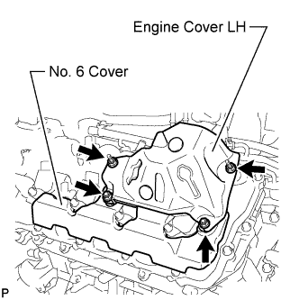
Remove the 4 nuts and engine cover LH.
-
-
REMOVE NO. 6 COVER SUB-ASSEMBLY
-
Remove the No. 6 cover.
-
-
REMOVE ENGINE COVER SUB-ASSEMBLY RH
-
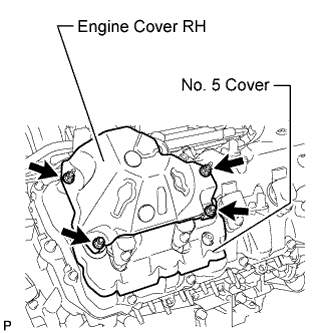
Remove the 4 nuts and engine cover RH.
-
-
REMOVE NO. 5 COVER SUB-ASSEMBLY
-
Remove the No. 5 cover.
-
-
REMOVE ENGINE WIRE
-
Engine LH Side:
-
Disconnect the camshaft timing control valve connector.
-
Disconnect the 4 ignition coil connectors.
-
Disconnect the 2 VVT sensor connectors.
-
Disconnect the fuel pump connector (for high pressure).
-
Disconnect the fuel injector connector.
-
Disconnect the 4 clamps.
-
-
Engine Front Side:
-
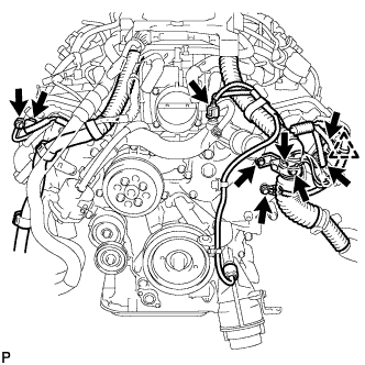
Disconnect the engine coolant temperature sensor connector.
-
Disconnect the 2 camshaft timing control motor connectors (for Bank 1).
-
Disconnect the 2 camshaft timing control motor connectors (for Bank 2).
-
Disconnect the clamp.
-
Remove the 3 bolts and disconnect the 3 ground wires.
-
-
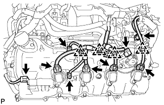
Engine RH Side:
-
Disconnect the camshaft timing control valve connector.
-
Disconnect the 4 ignition coil connectors.
-
Disconnect the 2 VVT sensor connectors.
-
Disconnect the fuel pump connector (for high pressure).
-
Disconnect the camshaft position sensor connector.
-
Disconnect the fuel injector connector.
-
Disconnect the 4 clamps.
-
-
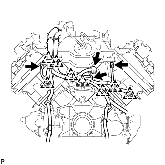
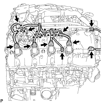
Engine Rear Side:
-
Disconnect the engine wire connector.
-
Disconnect the fuel relief valve connector.
-
Disconnect the 8 clamps.
-
Remove the 2 bolts and disconnect the 2 ground wires.
-
-
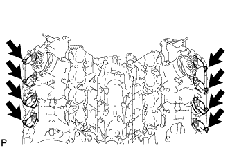
Engine Upper Side:
-
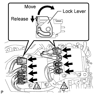
Disconnect the 8 injector connectors as shown in the illustration.
-
Disconnect the 2 clamps.
-
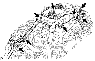
Disconnect the purge VSV connector.
-
Disconnect the intake air control valve actuator connector.
-
Disconnect the 2 clamps and remove the 2 bolts and 2 clamp brackets.
-
Remove the 4 nuts and remove the engine wire.
-
-
-
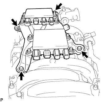
REMOVE INJECTOR DRIVER
-
Remove the 2 bolts, 2 nuts and 2 injector drivers with bracket.
Note
Be careful not to drop or strike the injector driver.
-
-
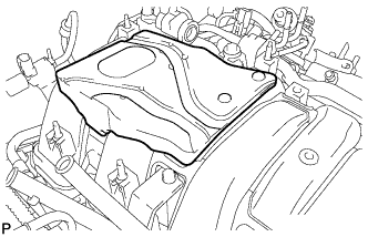
REMOVE NO. 1 ENGINE COVER
-
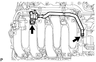
REMOVE PURGE VSV
-
Disconnect the purge line hose from the intake manifold.
-
Remove the bolt and purge VSV.
-
-
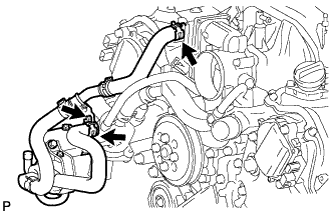
REMOVE HEATER WATER PUMP ASSEMBLY
-
Slide the 2 clamps, and disconnect the 2 hoses from the water inlet housing and water by-pass pipe.
-
Remove the bolt and heater water pump.
-
-
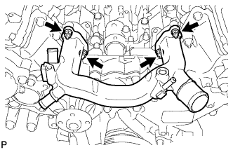
REMOVE WATER BY-PASS PIPE SUB-ASSEMBLY
-
Slide the clamp, and disconnect the water inlet hose from the front water by-pass joint.
-
Remove the 2 bolts and water by-pass pipe.
-
-
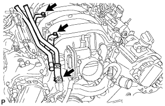
REMOVE INTAKE MANIFOLD ASSEMBLY
-
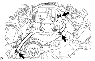
Disconnect the 2 water by-pass hoses and No. 1 ventilation hose as shown in the illustration.
-
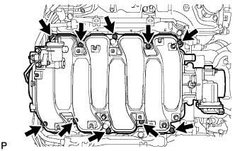
Remove the 8 bolts, 2 nuts and intake manifold.
-
Remove the 2 gaskets from the intake manifold.
-
-
REMOVE FUEL PRESSURE PULSATION DAMPER ASSEMBLY
-
REMOVE NO. 3 FUEL PIPE SUB-ASSEMBLY
-
Disconnect the fuel pump connector.
-
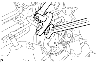
Fix the union bolt on the fuel pump side in place with a 21 mm wrench. Using a 19 mm union nut wrench, loosen the union nut and disconnect the No. 3 fuel pipe sub-assembly from the fuel pump.
Note
Do not loosen the union bolt on the fuel pump side. If the union bolt is accidentally loosened, replace the fuel pump.
-
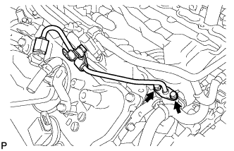
Remove the 2 bolts on the delivery pipe side and remove the No. 3 fuel pipe sub-assembly.
-
Remove the O-ring, backup rings and E-ring from the No. 3 fuel pipe sub-assembly.
-
-
REMOVE NO. 2 FUEL PIPE SUB-ASSEMBLY
Tech Tips
The removal procedures are the same as for the No. 3 fuel pipe sub-assembly.
-
REMOVE FUEL PUMP ASSEMBLY (for Bank 1)
-
Disconnect the fuel pump connector.
-
Remove the 2 nuts, fuel pump and fuel pump insulator.
-
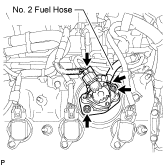
Disconnect the No. 2 fuel hose from the fuel pump.
-
-
REMOVE FUEL PUMP ASSEMBLY (for Bank 2)
-
Disconnect the fuel pump connector.
-
Remove the 2 nuts, fuel pump and fuel pump insulator.
-
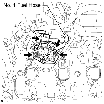
Disconnect the No. 1 fuel hose from the fuel pump.
-
-
REMOVE WATER INLET HOUSING
-
Using needle-nose pliers, grip the claws of the clip and slide the clip to disconnect the water inlet hose.
-
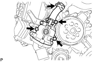
Remove the 3 bolts, water inlet housing and gasket.
-
-
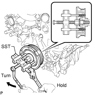
REMOVE WATER PUMP PULLEY
-
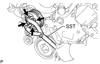
Using SST, hold the water pump pulley.
- SST
- 09960-10010 ( 09962-01000, 09963-01000 )
-
Remove the 4 bolts and water pump pulley.
-
-
REMOVE V-RIBBED BELT TENSIONER ASSEMBLY
-
Remove the bolt and belt tensioner.
-
-
REMOVE FRONT WATER BY-PASS JOINT
-
Remove the 4 nuts, water by-pass joint and 2 gaskets.
-
-
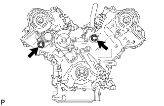
REMOVE CAMSHAFT TIMING CONTROL MOTOR ASSEMBLY LH
-
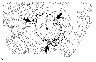
Remove the 3 bolts and camshaft timing control motor.
-
Remove the O-ring from the timing chain cover.
-
-
REMOVE CAMSHAFT TIMING CONTROL MOTOR ASSEMBLY RH
-
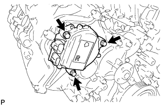
Remove the 3 bolts and camshaft timing control motor.
-
Remove the O-ring from the timing chain cover.
-
-
REMOVE OIL FILTER ELEMENT
-
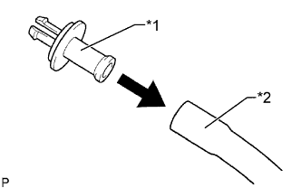
Text in Illustration *1 Pipe *2 Hose Connect a hose with an inside diameter of 15 mm (0.591 in.) to the pipe.
-
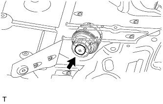
Remove the oil filter drain plug.
-
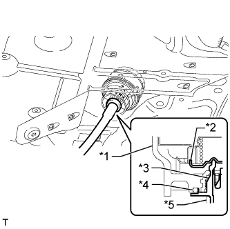
Text in Illustration *1 Oil Filter Cap *2 Valve *3 Pipe *4 O-Ring *5 Hose Install the pipe to the oil filter cap.
Note
If the O-ring is removed with the drain plug, install the O-ring together with the pipe.
Tech Tips
Use a container to catch the draining oil.
-
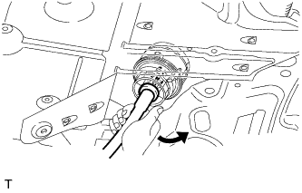
Check that oil is drained from the oil filter. Then disconnect the pipe and remove the O-ring as shown in the illustration.
-
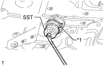
Text in Illustration *1 Oil Filter Bracket Clip Using SST, remove the oil filter cap.
- SST
- 09228-06501
Note
Do not remove the oil filter bracket clip.
-
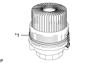
Text in Illustration *1 O-Ring Remove the oil filter element and O-ring from the oil filter cap.
Note
Be sure to remove the cap's O-ring by hand, without using any tools, to prevent damage to the cap's O-ring groove.
-
-
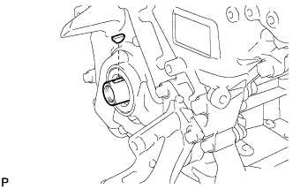
REMOVE OIL FILTER BRACKET
-
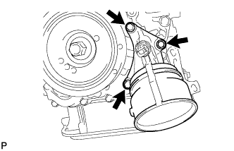
Remove the 3 bolts, filter bracket and 2 gaskets.
-
-
REMOVE CRANKSHAFT PULLEY
-
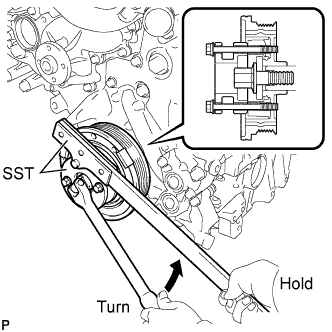
Using SST, loosen the crankshaft pulley set bolt until 2 or 3 threads are engaged.
- SST
- 09213-54015 ( 90119-08216 )
- 09330-00021
-
Using the pulley set bolt and SST, remove the crankshaft pulley.
- SST
- 09950-50013 ( 09951-05010, 09952-05010, 09953-05010, 09954-05031 )
-
-
REMOVE CRANKSHAFT TIMING GEAR KEY
-
Remove the crankshaft timing gear key from the crankshaft.
-
-
REMOVE IGNITION COIL ASSEMBLY
-
Remove the 8 bolts and 8 ignition coils.
-
-
REMOVE CYLINDER HEAD COVER SUB-ASSEMBLY LH
-
Remove the fuel pump spacer.
-
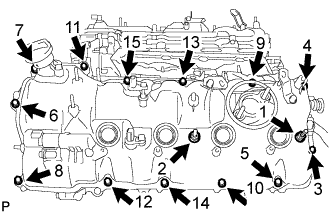
Remove the 15 bolts in the order shown in the illustration. Then remove the 2 seal washers, cylinder head cover and gasket.
Tech Tips
Make sure the removed parts are returned to the same places they were removed from.
-
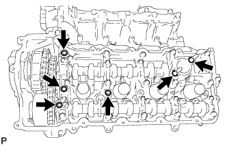
Remove the 4 gaskets and 2 O-rings from the camshaft bearing caps (No. 2, No. 3 and No. 7).
-
-
REMOVE CYLINDER HEAD COVER SUB-ASSEMBLY RH
-
Remove the fuel pump spacer.
-
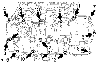
Remove the 15 bolts in the order shown in the illustration. Then remove the 2 seal washers, cylinder head cover and gasket.
Tech Tips
Make sure the removed parts are returned to the same places they were removed from.
-
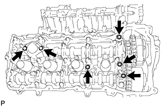
Remove the 4 gaskets and 2 O-rings from the camshaft bearing caps (No. 1, No. 3 and No. 6).
-
-
REMOVE TIMING CHAIN COVER SUB-ASSEMBLY
-
Remove the 2 plugs and 2 gaskets.
-
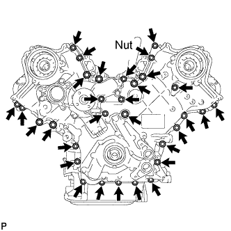
Remove the 30 bolts and nut shown in the illustration.
-
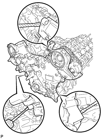
Remove the timing chain cover by prying between the timing chain cover and cylinder head or cylinder block with a screwdriver as shown in the illustration.
Note
Be careful not to damage the contact surfaces of the cylinder head, cylinder block and chain cover.
Tech Tips
Tape the screwdriver tip before use.
-
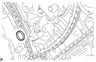
Remove the oil pump gasket from the cylinder block.
-
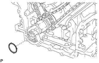
Remove the O-ring from the oil pan.
-
-
REMOVE WATER INLET PIPE
-
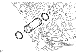
Remove the water inlet pipe.
-
Remove the 2 O-rings from the water inlet pipe.
-
-
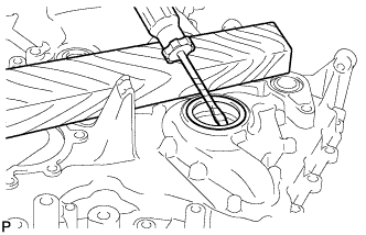
REMOVE FRONT CRANKSHAFT OIL SEAL
-
Place the timing chain cover on wooden blocks.
-
Using a screwdriver and wooden block, pry out the oil seal.
Note
Do not damage the surface of the oil seal press fit hole.
Tech Tips
Tape the screwdriver tip before use.
-