RADIATOR INSTALLATION

-
INSTALL LOWER RADIATOR SUPPORT
-
Install the 2 lower radiator supports.
-
-
INSTALL RADIATOR SUPPORT CUSHION
-
Install the 2 radiator support cushions.
-
-
INSTALL COOLER CONDENSER ASSEMBLY
-
Install the cooler condenser assembly to the radiator assembly with the 4 bolts.
- Torque:
- 6.0 N*m { 61 kgf*cm, 53 in.*lbf }
-
-
INSTALL FAN SHROUD WITH FAN AND MOTOR
-
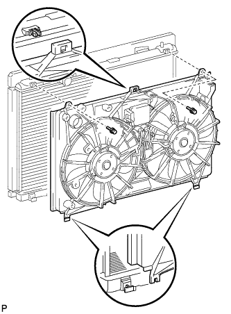
Set the fan shroud with fan and motor to the radiator assembly, and attach the claw.
-
Install the fan shroud with fan and motor with the 2 bolts.
- Torque:
- 7.1 N*m { 72 kgf*cm, 63 in.*lbf }
-
-
INSTALL RADIATOR ASSEMBLY
-
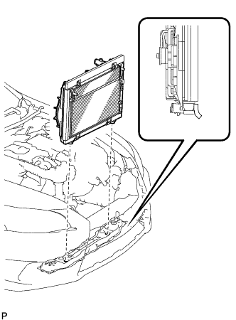
Install the radiator assembly to the front crossmember.
Note
Do not allow the radiator assembly to interfere with other parts.
Tech Tips
Install the radiator assembly to the front side holes of the lower support of the radiator assembly.
-
-
CONNECT LIQUID TUBE SUB-ASSEMBLY A
-
Remove the attached vinyl tape from the pipe and the connecting part of the cooler condenser.
-
Sufficiently apply compressor oil to a new O-ring and the fitting surface of the pipe joint.
Compressor oil ND-OIL 11 or equivalent -
Install the O-ring to the liquid tube.
-
Install the liquid tube to the cooler condenser with the 2 bolts.
- Torque:
- 5.4 N*m { 55 kgf*cm, 48 in.*lbf }
Note
-
When tightening the bolt, do not allow any tools to contact the pipe.
-
When tightening the bolt, hold a part of the pipe near the connector.
-
-
CONNECT DISCHARGE HOSE SUB-ASSEMBLY
-
Remove the attached vinyl tape from the discharge hose sub-assembly and the connecting part of the cooler condenser.
-
Sufficiently apply compressor oil to a new O-ring and the fitting surface of the hose joint.
Compressor oil ND-OIL 11 or equivalent -
Install the O-ring to the discharge hose sub-assembly.
-
Install the discharge hose sub-assembly to the cooler condenser with the bolt.
- Torque:
- 5.4 N*m { 55 kgf*cm, 48 in.*lbf }
Note
-
When tightening the bolt, do not allow any tools to contact the pipe.
-
When tightening the bolt, hold a part of the pipe near the connector.
-
-
CONNECT NO. 1 INVERTER COOLING HOSE
-
Connect the No. 1 inverter cooling hose and install the clip.
-
-
CONNECT NO. 2 INVERTER COOLING HOSE
-
Connect the No. 2 inverter cooling hose and install the clip.
-
-
INSTALL HOOD LOCK ASSEMBLY
-
Install the hood lock assembly to the hood lock control cable.
-
-
INSTALL HOOD LOCK CONTROL CABLE COVER
-
Connect the wire harness clamp to the hood lock control cable cover.
-
Connect the hood lock control cable to the hood lock control cable cover.
-
Attach the guide to install the hood lock control cable cover.
-
-
INSTALL RADIATOR UPPER SUPPORT SUB-ASSEMBLY
-
Connect the 3 connectors and 5 wire harness clamps to connect the wire harness.
-
Install the radiator upper support sub-assembly with the 5 bolts.
- Torque:
- 8.0 N*m { 82 kgf*cm, 71 in.*lbf }
-
-
CONNECT WIRE HARNESS
-
Attach the 8 wire harness clamps to fan shroud and connect the 3 connectors.
-
-
CONNECT HOOD LOCK ASSEMBLY
-
Connect the connector.
-
Connect the hood lock assembly with the 2 bolts and lock nut.
- Torque:
- 8.0 N*m { 82 kgf*cm, 71 in.*lbf }
-
Install the lock nut cap.
-
-
CONNECT HOOD LOCK CONTROL CABLE COVER
-
Connect the hood lock control cable cover with the 3 screws and attach the claw.
-
-
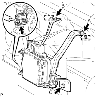
INSTALL MILLIMETER WAVE RADAR SENSOR ASSEMBLY (w/ Dynamic Radar Cruise Control System)
-
Connect the connector.
-
Attach the 2 guides and install the millimeter wave radar sensor assembly with the 3 bolts in alphabetical order.
- Torque:
- 5.5 N*m { 56 kgf*cm, 49 in.*lbf }
-
-
INSTALL OUTLET ENGINE ROOM ECU DUCT
-
Install the outlet engine room ECM duct.
-
-
CONNECT NO. 2 OIL COOLER OUTLET HOSE
-
Connect the No. 2 oil cooler outlet hose to the radiator assembly.
-
-
CONNECT NO. 2 OIL COOLER INLET HOSE
-
Connect the No. 2 oil cooler inlet hose to the radiator assembly.
-
-
INSTALL NO. 2 RADIATOR HOSE
-
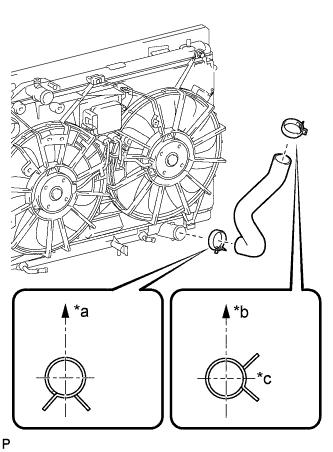
Text in Illustration *a Upper *b Front Side of Vehicle *c RH Side Install the No. 2 radiator hose.
Tech Tips
The direction of each hose clamp is indicated in the illustration.
-
-
INSTALL NO. 1 RADIATOR HOSE
-
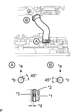
Text in Illustration *1 No. 1 Radiator Hose *2 Hose Clamp *3 Stopper *a Upper *b RH Side *c LH Side *d 1.0 to 5.0 mm (0.0393 to 0.197 in.) Install the No. 1 radiator hose to the radiator and water outlet, and then secure it with the hose clamps.
Tech Tips
-
The direction of each hose clamp is indicated in the illustration.
-
Insert the No. 2 radiator hose into the stopper. Set each hose clamp so that the clearance between the hose clamp and the stopper is within 1.0 to 5.0 mm (0.0393 to 0.197 in.).
-
-
-
INSTALL RADIATOR RESERVOIR ASSEMBLY
-
Install the radiator reservoir assembly with the 2 bolts.
- Torque:
- 5.0 N*m { 51 kgf*cm, 44 in.*lbf }
-
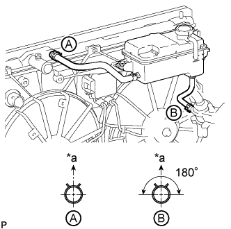
Text in Illustration *a Upper Connect the 2 reservoir hoses.
Tech Tips
The direction of each hose clamp is indicated in the illustration.
-
-
ADD COOLANT (for Inverter)
Note
-
Do not reuse the drained coolant because it may contain foreign objects.
-
If the vehicle is driven with air in the inverter cooling system, the following DTCs may be set.
DTC Code Detection Item P0A01-725 Motor Electronics Coolant Temperature Sensor Circuit Range / Performance P0A01-726 Motor Electronics Coolant Temperature Sensor Circuit Range / Performance P0A78-284 Drive Motor "A" Inverter Performance P0A7A-322 Generator Inverter Performance P0A93-346 Inverter Cooling System Performance P0A94-553 DC / DC Converter Performance P0AEE-276 Motor Inverter Temperature Sensor "A" Circuit Range / Performance P0AEE-277 Motor Inverter Temperature Sensor "A" Circuit Range / Performance P3221-314 Generator Inverter Temperature Sensor Circuit Range / Performance P3221-315 Generator Inverter Temperature Sensor Circuit Range / Performance P3226-562 DC/DC Boost Converter Temperature Sensor P3226-563 DC/DC Boost Converter Temperature Sensor
Tech Tips
-
for LHD:
Coolant (for inverter) capacity: 2.6 liters (2.7 US qts, 2.3 Imp. qts.)
-
for RHD:
Coolant (for inverter) capacity: 2.5 liters (2.5 US qts, 2.2 Imp. qts.)
-
for LHD:
Remove the 2 clips and 2 plugs from the tubes.
Note
Do not reuse the clips or plugs.
-
for RHD:
Remove the clip and plug from the tube.
Note
Do not reuse the clip or plug.
-
Add coolant to the reserve tank.
-
for LHD:
Install 2 new plugs and 2 new clips to the tubes.
-
for RHD:
Install a new plug and new clip to the tube.
-
Connect the intelligent tester to the DLC3.
-
Select the following menu items: Powertrain / Hybrid Control / Active Test / Activate the Water Pump.
Tech Tips
The water pump can also be operated using inspection mode Click here.
-
While adding coolant so that the coolant level is kept around the FULL line of the inverter reserve tank, operate the water pump for 3 minutes or more and then stop it for 1 minute or more.
-
While adding coolant so that the coolant level is kept around the FULL line of the inverter reserve tank, operate the water pump for 1 minute or more and stop it for 1 minute or more. Repeat this procedure until bleeding is completed.
Standard When the operation sound of the water pump becomes small or when no air bubbles can be seen in the inverter reserve tank, bleeding of the coolant system is complete. Tech Tips
-
If the water pump operates without a sufficient amount of coolant for approximately 5 seconds, the protective circuit will activate to stop the water pump for approximately 15 seconds. If a sufficient amount of coolant is added, the water pump will start operating automatically.
-
If an excessive amount of coolant is added to the inverter reserve tank, coolant may overflow when operation of the water pump is stopped.
-
-
After bleeding is completed, add coolant to the FULL level, and install the inverter reserve tank cap.
Note
Make sure to add more coolant than was drained initially.
-
-
ADD ENGINE COOLANT
CAUTION:
Do not remove the radiator reservoir cap while the engine and radiator are still hot. Pressurized, hot coolant and steam may be released and cause serious burns.
Tech Tips
Before adding coolant, turn the A/C switch off.
Total capacity 11.1 liters (11.7 US qts, 9.8 Imp. qts)
-
Tighten the radiator drain cock plug.
-
Tighten the 2 cylinder block drain cock plugs.
- Torque:
- 13 N*m { 133 kgf*cm, 10 ft.*lbf }
-
Add TOYOTA Super Long Life Coolant (SLLC) into the radiator reservoir.
Capacity 5.0 liters (5.3 US qts, 4.4 Imp. qts) Tech Tips
TOYOTA vehicles are filled with TOYOTA SLLC at the factory. In order to avoid damage to the engine cooling system and other technical problems, only use TOYOTA SLLC or similar high quality ethylene glycol based non-silicate, non-amine, non-nitrite, non-borate coolant with long-life hybrid organic acid technology (coolant with long-life hybrid organic acid technology consists of a combination of low phosphates and organic acids).
-
Further add coolant into the reservoir until it reaches the FULL line.
-
Press the No. 1 and No. 2 radiator hoses several times by hand, and then check the coolant level.
If the coolant level is low, add coolant.
-
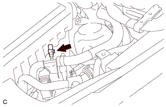
Using a 6 mm hexagon wrench, install the vent plug.
- Torque:
- 1.5 N*m { 15 kgf*cm, 13 in.*lbf }
-
Bleed air from the cooling system.
Tech Tips
Before starting the engine to warm up the engine, turn the A/C switch off.
-
Put the engine in inspection mode Click here.
-
While idling the engine for approximately 10 minutes, make sure the coolant remains at the FULL line by adding coolant as necessary.
-
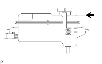
After idling the engine for 10 minutes, add coolant until it reaches the B line.
Capacity 2.5 to 3.5 liters (2.6 to 3.7 US qts, 2.2 to 3.1 Imp. qts) Text in Illustration 
B Line Tech Tips
The B line is the lower edge of the inner wall of the filler neck.
-
Close the radiator reservoir cap, and run the engine at 1500 to 2000 rpm for 5 minutes.
CAUTION:
-
Wear protective gloves.
-
Be careful as the radiator hose is hot.
-
Keep your hands away from the radiator fan.
Tech Tips
The thermostat open timing can be confirmed by pressing the No. 1 radiator hose by hand, and checking when the SLLC starts to flow inside the hose.
-
-
-
Stop the engine and wait until the coolant cools down to ambient temperature.
-
Check the coolant level.
If the coolant level is below the FULL line, add coolant until it reaches the FULL line.
-
-
CHARGE REFRIGERANT
-
Perform vacuum purging using a vacuum pump or appropriate equipment.
-
Charge the air conditioning system with refrigerant.
Refrigerant type HFC-134a (R134a) 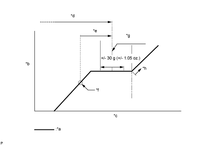
Text in Illustration *a Sub-cool System *b High Pressure *c Refrigerant Amount *d Standard charge amount *e Charge additional 100 g (3.5 oz.) *f Point where bubbles disappear *g Mean value in proper range *h Overcharged Standard charge amount 810 to 870 g (28.6 to 30.7 oz.) - SST
- 09985-20010 ( 09985-02010, 09985-02050, 09985-02060, 09985-02070, 09985-02080, 09985-02090, 09985-02110, 09985-02130, 09985-02140, 09985-02150 )
Note
-
Do not turn the A/C switch on before charging the air conditioning system with refrigerant. Doing so may cause the compressor to work without refrigerant, resulting in overheating of the compressor.
-
The refrigerant amount should be checked by quantity (weight).
Tech Tips
Make sure that sufficient refrigerant is available to recharge the system when using a refrigerant recovery unit. Refrigerant recovery units are not always able to recover 100% of the refrigerant from an air conditioning system.
-
-
CHECK TRANSMISSION FLUID LEVEL
CAUTION:
Do not touch any high temperature parts, such as the exhaust pipe.
-
for Vehicles used in Middle East and China:
-
Turn the power switch on (READY).
-
Move the shift lever to P, depress the accelerator pedal and start the engine.
Tech Tips
Depending on the amount of battery charge, the engine may already be running.
Note
Check State of Charge in the Data List. If the Battery State of Charge value is less than 50%, return to the Check SOC procedure and perform charging again.
-
Release the accelerator pedal, depress the brake pedal, and move the shift lever to N while the engine is running.
-
Check Engine Spd in the Data List. Check that the engine speed is 950 to 1050 rpm.
-
In order to be able to check the Data List, take the intelligent tester out of the vehicle while it is still connected and lift the vehicle up while keeping the vehicle level.
-
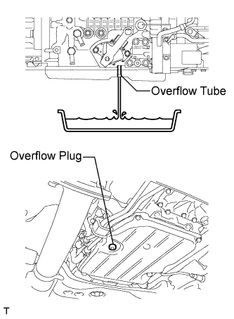
Remove the overflow plug and gasket.
-
When the fluid overflowing from the overflow tube slows to a trickle, check T/M Oil Temperature in the Data List. When the value reaches 50°C (122°F), install a new gasket and the overflow plug.
- Torque:
- 20 N*m { 204 kgf*cm, 15 ft.*lbf }
Note
If the Battery State of Charge value is 30% or less at this time, stop work, return to the Check SOC procedure and start the procedure again from the step in which the battery is charged.
-
-
except Vehicles used in Middle East and China:
-
When the indicator light (D) turns on, lift the vehicle up immediately.
The ATF temperature range is indicated by the indicator light (D) Below Normal Operating Temperature Normal Operating Temperature Above Normal Operating Temperature OFF ON Blinking Note
Perform the fluid level inspection while the indicator light is on.
-
Remove the overflow plug. At the normal operating temperature, check the fluid amount.
If the ATF flows from the overflow tube in a thin stream, the fluid amount is normal.
-
Install a new gasket and the overflow plug.
- Torque:
- 20 N*m { 204 kgf*cm, 15 ft.*lbf }
-
-
-
INSPECT FOR COOLANT LEAK (for Inverter)
-
Remove the reserve tank cap.
CAUTION:
To avoid the danger of being burned, do not remove the reserve tank cap while the coolant for the inverter is still hot.
-
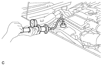
Install the radiator cap tester.
-
Pump the radiator cap tester to 37 kPa (0.38 kgf/ cm2, 5.4 psi), and then check that the pressure does not drop.
Tech Tips
If the pressure drops, check the hoses, radiator, water pump, inverter with converter, and hybrid vehicle transaxle assembly for leakage.
-
Reinstall the reserve tank cap.
-
-
INSPECT FOR COOLANT LEAK
CAUTION:
Do not remove the radiator reservoir cap while the engine and radiator are still hot. Pressurized, hot engine coolant and steam may be released and cause serious burns.
Note
Before each inspection, turn the A/C switch OFF.
-
Fill the radiator with coolant and attach a radiator cap tester.
-
Warm up the engine.
-
Using the radiator cap tester, increase the pressure inside the radiator to 118 kPa (1.2 kgf/cm2, 17 psi), and check that the pressure does not drop.
If the pressure drops, check the hoses, radiator and engine water pump for leaks. If no external leaks are found, check the heater core, cylinder block and head.
-
-
INSPECT FOR REFRIGERANT LEAK
-
After recharging the air conditioning system with refrigerant, check for refrigerant leaks using a halogen leak detector.
-
Carry out the test under the following conditions:
-
Power switch off.
-
Secure good ventilation (the halogen leak detector may react to volatile gases which are not refrigerant, such as gasoline vapor and exhaust gas).
-
Repeat the inspection 2 or 3 times.
-
Measure the pressure to make sure that there is some refrigerant remaining in the air conditioning system (pressure when the compressor is off: approx. 392 to 588 kPa (3.9 to 5.9 kgf/cm2, 57 to 85 psi)).
-
-
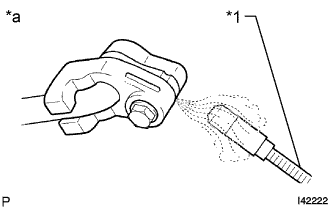
Text in Illustration *1 Halogen Leak Detector *a Check for Leak Using a halogen leak detector, check for refrigerant leaks from the air conditioning system.
-
If a refrigerant leak is not detected from the drain hose, remove the blower motor control from the cooling unit. Insert the halogen leak detector sensor into the unit and check for a leak.
-
Disconnect the pressure sensor connector and leave it for approximately 20 minutes. Bring the halogen leak detector close to the pressure sensor and check for a leak.
Tech Tips
When checking for leaks, the presence of oily dirt at a joint can indicate a leak.
-
-
ADJUST MILLIMETER WAVE RADAR SENSOR ASSEMBLY (w/ Dynamic Radar Cruise Control System)
CAUTION:
Exposure to radio frequency emissions is hazardous to your health. It is hazardous to be within 20 cm (7.87 in.) of the device's radio frequency aperture.
Note
-
This device complies with FCC radio frequency emission regulations.
-
Perform measurements on a level surface.
-
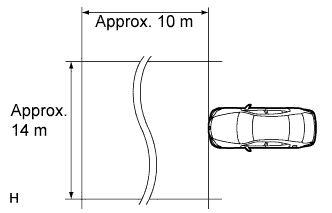
Make sure that no large pieces of metal are within a 10 m (32.8 ft.) x 14 m (45.9 ft.) area in front of the vehicle. If possible, the surrounding area should also be free of large metal objects.
-
Before adjusting the radar beam axis, prepare the vehicle as follows.
-
Check the tire pressure and adjust it if necessary.
-
Remove all excess weight from the vehicle (luggage, heavy objects, etc.).
-
-
w/ Air Suspension:
Adjust the vehicle's height to the standard height.
-
Check and adjust the vertical direction of the radar sensor.
-
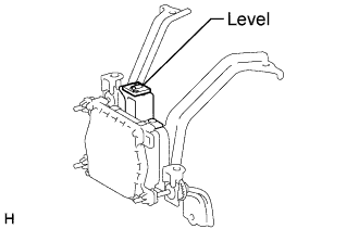
Remove dust, oil and foreign matter from the radar sensor's level rack.
-
Set a level on the radar sensor's level rack.
-
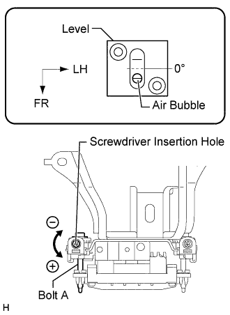
Check that the level's air bubble is within the red frame.
OK Level's air bubble is within red frame. If the bubble is not within the red frame, use a screwdriver to adjust bolt A until the level's air bubble is within the red frame.
Tech Tips
-
The adjustable range within the red frame of the level is +/-0.2°.
-
The target angle is +0.2° (upward angle of 0.2°).
Result Adjustment Direction Adjustment Procedure Adjustment Angle Vertical adjustment Upward direction: Turn bolt A in minus (- )direction For 1 complete turn of screwdriver, sensor moves about 0.12° Downward direction: Turn bolt A in plus (+) direction -
-
-
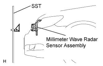
Adjust the reflector height.
-
Adjust the reflector so that the center of SST reflector is the same height as the millimeter wave radar sensor.
- SST
- 09870-60000 ( 09870-60010 )
- 09870-60040
Tech Tips
Prepare a 10 m (32.8 ft.) string, a string with a sharp-pointed weight (plumb bob), and a 5 m (16.4 ft.) tape measure.
-
-
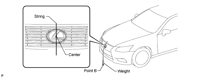
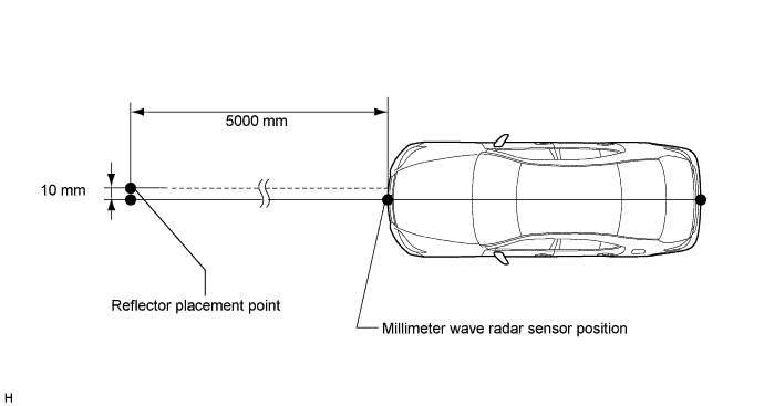
Place the reflector.
-
From the center of the front bumper (center of the emblem), hang a weight with a pointed tip, and mark point B on the ground.
-
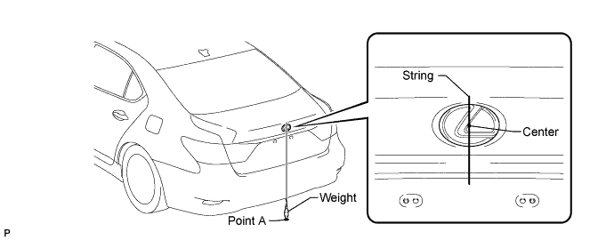
From the center of the rear bumper (center of the emblem), hang a weight with a pointed tip, and mark point A on the ground.
-
Using a piece of string that uses point A as a starting point and that passes through point B, make a straight line on the ground ahead of the vehicle 5 m (16.4 ft.) or more from point B.
Tech Tips
-
Make sure to secure the string (using tape, etc.) when it is taut.
-
Lightly flick the string with your fingers several times to confirm that the string is aligned above point B.
-
-
Using a tape measure, measure 10 mm (0.394 in.) to the left of the 5000 mm (16.4 ft.) position. Place the reflector at that position.
Note
Perform the operation as precisely as possible.
-
-
Check the radar beam axis.
-
Connect the intelligent tester to the DLC3.
-
Turn the power switch on (IG).
-
Turn the intelligent tester main switch ON, and turn the cruise control main switch ON.
-
Select "Auto" from the intelligent tester display screen. *1
-
Select "Radar Cruise" from the display screen.
-
Select the appropriate menu item.
-
For vehicles with lane recognition camera: select "w/ LKA System" from the display screen.
-
For vehicles without lane recognition camera: select "w/o LKA System" from the display screen.
-
-
Select "Radar Cruise" from the display screen.
-
Select "Utility" from the display screen.
-
Select "Beam Axis Adjustment" from the display screen.
-
Follow the intelligent tester display and select "Next".
Note
-
Turn the cruise control main switch ON before pressing Next.
-
Make sure there is at least 20 cm (7.9 inches) between the radar sensor and any nearby individuals.
CAUTION:
Do not come within 20 cm (7.9 inches) of the radar sensor.
-
-
Check the following items on the laser cruise divergence data screen.
CAUTION:
While using the intelligent tester's beam axis adjustment mode, the actual direction and angle of the radar sensor may be different from the intelligent tester's data. In such a case, the deviation is displayed on the combination meter's multi-information display.
-
Confirm that the distance value is approximately 5 m (16.4 ft.).
Tech Tips
-
A value between 0.0 and 6.3 m (20.7 ft.) is indicated.
-
If the distance is 0 m (0 ft.), the sensor cannot detect the target. Reconfirm that there is no metal in the specified area in front of the vehicle (refer to the NOTICE at the beginning of this adjustment procedure).
-
-
Confirm that the left/right side value is between 0.0 and 6.3°.
Tech Tips
If the distance is 0 m (0 ft.), the sensor cannot detect the target. Reconfirm that there is no metal in the specified area in front of the vehicle (refer to the NOTICE at the beginning of this adjustment procedure).
-
-
-
Check and adjust the horizontal direction of the radar sensor.
-
Check that the divergence of the radar beam axis is 0°.
Standard 0° (Both right and left) If the axis is not as specified, use a screwdriver to adjust bolt B until the divergence of the radar beam axis is 0°.
-
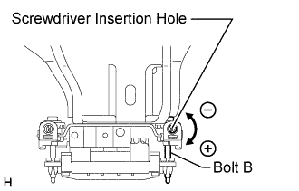
Based on the measured divergence of the beam axis, turn and adjust bolt B for horizontal adjustment of the millimeter wave radar sensor using a screwdriver.
Result Adjustment Direction Adjustment Procedure Adjustment Angle Horizontal adjustment Right direction: Turn bolt B in plus (+) direction For 1 complete turn of screwdriver, sensor moves about 0.07° Left direction: Turn bolt B in minus (- )direction Tech Tips
If the value does not change to 0°, it is possible that the sensor is aiming at something different. Reconfirm that there are no reflective materials in the surrounding area.
-
Select "Next". The driving learning value is automatically reset.
Tech Tips
A buzzer will sound for 10 seconds or more.
-
Disconnect the intelligent tester from the DLC3.
-
-
Recheck and readjust the vertical direction of the radar sensor.
-
Set a level on the radar sensor's level rack.
-
Check that the level's air bubble is within the red frame.
OK Level's air bubble is within the red frame. If the bubble is not within the red frame, use a screwdriver to adjust bolt A until the level's air bubble is within the red frame.
Tech Tips
-
The adjustable range within the red frame is +/-0.2°.
-
The target angle is +0.2° (upward angle of 0.2°).
Result Adjustment Direction Adjustment Procedure Adjustment Angle Vertical adjustment Upward direction: Turn bolt A in minus (- )direction For 1 complete turn of screwdriver, sensor moves about 0.12° Downward direction: Turn bolt A in plus (+) direction -
-
-
-
INSTALL FRONT CENTER FLOOR COVER (w/ Cover)
-
Install the front center floor cover with the 3 screws, 2 bolts and clip.
- Torque:
- 5.4 N*m { 55 kgf*cm, 48 in.*lbf }
-
-
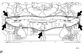
INSTALL NO. 1 ENGINE UNDER COVER
-
Install the No. 1 engine under cover with the 13 screws and 7 clips.
-
-
INSTALL NO. 1 AIR CLEANER INLET
-
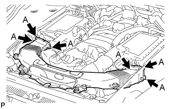
Align the holes with the connection areas labeled A, and attach the No. 1 air cleaner inlet.
-
Install the No. 1 air cleaner inlet with the 2 bolts.
- Torque:
- 5.0 N*m { 51 kgf*cm, 44 in.*lbf }
-
-
INSTALL V-BANK COVER SUB-ASSEMBLY
-

After sliding the V-bank cover sub-assembly from the vehicle front to the rear to attach the 2 clips labeled A, attach the 4 clips labeled B and install the V-bank cover sub-assembly.
CAUTION:
-
Make sure the clips are attached securely.
-
Attaching the clips forcefully or hitting the top of the clips may damage them.
-
-
-
INSTALL FRONT BUMPER REINFORCEMENT