WATER PUMP REMOVAL

-
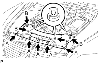
REMOVE V-BANK COVER SUB-ASSEMBLY
-

While using both hands, lift the rear side of the V-bank cover sub-assembly upwards to detach the 4 clips labeled B. Slide the V-bank cover sub-assembly towards the front of the vehicle to detach the 2 clips labeled A, and remove the V-bank cover sub-assembly.
Note
The V-bank cover sub-assembly may be damaged if its front and rear are lifted at the same time.
-
-
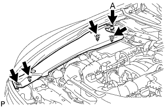
REMOVE AIR CLEANER INLET COVER SUB-ASSEMBLY
-
Remove the 5 clips labeled A.
-
Lift up the air cleaner inlet cover sub-assembly to detach the 4 clips labeled B, and remove the air cleaner inlet cover sub-assembly.
-
-
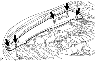
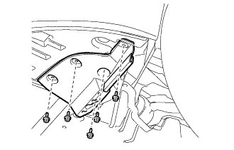
REMOVE ENGINE ROOM SIDE COVER RH
-
for LHD:
Remove the 5 clips and engine room side cover RH.
Note
Remove the clip labeled A by turning it to prevent the engine room side cover RH and bracket from being damaged.
Tech Tips
The clip labeled A cannot be removed from the engine room side cover RH.
-
for RHD:
Remove the 5 clips and engine room side cover RH.
-
-
REMOVE NO. 1 AIR CLEANER INLET
-
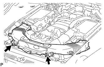
Remove the 2 bolts.
-
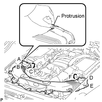
Hold the No. 1 air cleaner inlet by the protrusions labeled A and B, and detach the connections.
-
Rotate the No. 1 air cleaner inlet as shown in the illustration to detach the protrusion labeled C.
-
Hold the No. 1 air cleaner inlet by the protrusions labeled D and E, and detach the connections.
-
Rotate the No. 1 air cleaner inlet as shown in the illustration to detach the protrusion labeled F.
-
-
REMOVE FRONT WHEEL OPENING EXTENSION PAD LH
-
Remove the 5 screws and front wheel opening extension pad LH.
-
-
REMOVE FRONT WHEEL OPENING EXTENSION PAD RH
Tech Tips
Use the same procedure described for the LH side.
-
REMOVE NO. 1 ENGINE UNDER COVER
-
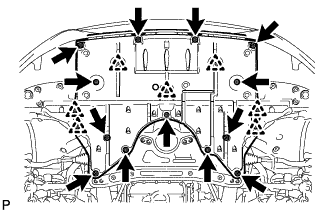
Remove the 13 screws, 7 clips and No. 1 engine under cover.
-
-
DRAIN ENGINE COOLANT
CAUTION:
Do not remove the radiator reservoir cap and vent plug while the engine and radiator are still hot. Pressurized, hot engine coolant and steam may be released and cause serious burns.
-
Loosen the radiator drain cock plug.
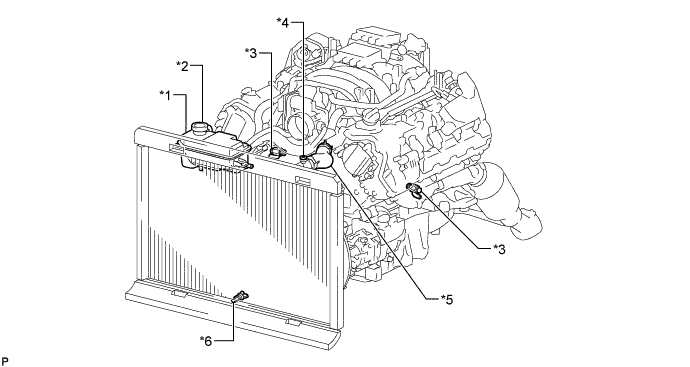
Text in Illustration *1 Radiator Reservoir *2 Radiator Reservoir Cap *3 Cylinder Block Drain Cock Plug *4 Vent Plug *5 No. 1 Radiator Hose *6 Radiator Drain Cock Plug Tech Tips
Collect the coolant in a container and dispose of it according to the regulations in your area.
-
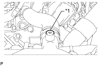
Text in Illustration *1 Vent Plug Remove the radiator reservoir cap, and using a 6 mm hexagon wrench, remove the vent plug.
-
Drain the coolant.
-
Loosen the 2 cylinder block drain cock plugs.
-
-
REMOVE RADIATOR RESERVOIR ASSEMBLY
-
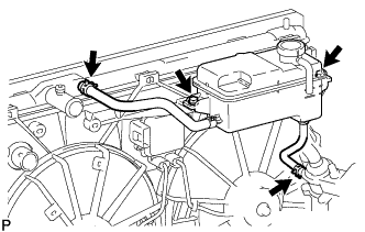
Disconnect the 2 reservoir hoses.
-
Remove the 2 bolts and radiator reservoir assembly.
-
-
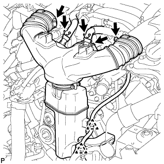
REMOVE INTAKE AIR CONNECTOR PIPE
-
Disconnect the No. 1 ventilation hose and No. 2 ventilation hose from the intake air connector pipe.
-
Using a clip remover, detach the 2 wire harness clamps.
-
Loosen the 3 hose clamps, and remove the intake air connector pipe.
-
-
REMOVE V-RIBBED BELT
-
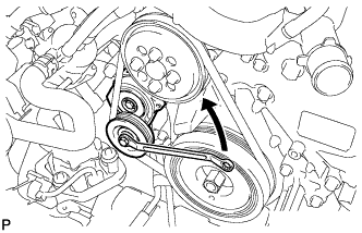
Rotate the tensioner pulley counterclockwise to loosen the V-ribbed belt tension assembly.
Tech Tips
The pulley bolt for the V-ribbed belt tensioner assembly has a left-handed thread.
-
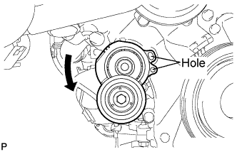
While turning the V-ribbed belt tensioner assembly counterclockwise, align the holes. Insert a bar with a diameter of 5 mm (0.197 in.) into the holes to fix the V-ribbed belt tensioner assembly in place.
-
Remove the V-ribbed belt.
-
-
DISCONNECT NO. 2 RADIATOR HOSE
-
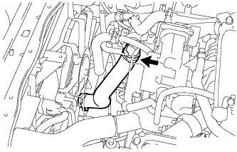
Disconnect the No. 2 radiator hose from the water inlet housing.
-
-
DISCONNECT WATER HOSE SUB-ASSEMBLY
-
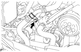
Remove the bolt and disconnect the water hose.
-
-
DISCONNECT WIRE HARNESS
-
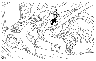
Remove the bolt and disconnect the wire harness.
-
-
DISCONNECT NO. 5 WATER BY-PASS HOSE
-
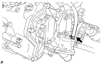
Using needle-nose pliers, grip the claws of the clip and slide the clip to disconnect the No. 5 water by-pass hose.
-
-
DISCONNECT WATER INLET HOSE
-
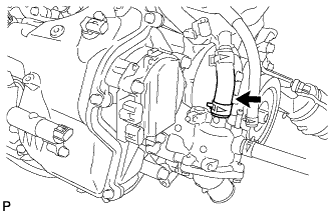
Using needle-nose pliers, grip the claws of the clip and slide the clip to disconnect the water inlet hose.
-
-
DISCONNECT INLET HEATER WATER HOSE
-
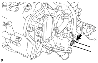
Using needle-nose pliers, grip the claws of the clip and slide the clip to disconnect the inlet heater water hose.
-
-
REMOVE WATER INLET HOUSING
-
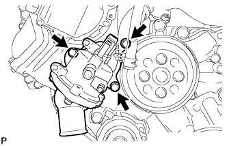
Remove the 3 bolts, water inlet housing and gasket.
-
-
REMOVE WATER PUMP PULLEY
-
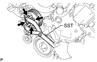
Using SST, hold the water pump pulley.
- SST
- 09960-10010 ( 09962-01000, 09963-01000 )
-
Remove the 4 bolts and water pump pulley.
-
-
REMOVE ENGINE WATER PUMP ASSEMBLY
-
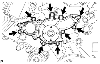
Remove the 9 bolts, engine water pump and gasket.
-