EXHAUST PIPE REMOVAL

CAUTION:
-
The procedures should be performed by at least 2 people.
-
Wear protective gloves when removing the exhaust pipe.
-
The exhaust pipe is extremely hot immediately after the engine has stopped.
-
Confirm that the exhaust pipe has cooled down before removing it.
Tech Tips
When viewed from the rear of the engine assembly, Bank 1 is on the left side and Bank 2 is on the right side.
-
REMOVE NO. 2 DIFFERENTIAL SUPPORT PROTECTOR
-
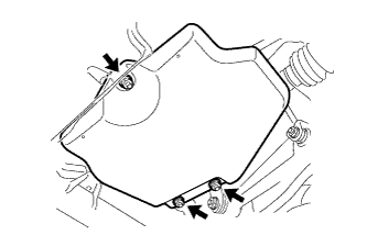
Remove the 3 nuts and differential support protector.
-
-
REMOVE NO. 1 DIFFERENTIAL SUPPORT PROTECTOR
Tech Tips
Use the same procedure described for the No. 2 differential support protector.
-
REMOVE NO. 6 ROCKER PANEL MOULDING PROTECTOR
-
Remove the 2 clips, screw and No. 6 rocker panel moulding protector.
-
-
REMOVE NO. 5 ROCKER PANEL MOULDING PROTECTOR
-
Remove the 2 clips, screw and No. 5 rocker panel moulding protector.
-
-
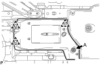
REMOVE REAR FLOOR SIDE MEMBER COVER LH
-
Remove the 3 clips, 2 screws, nut, bolt and rear floor side member cover LH.
Text in Illustration 
Bolt 
Nut 
Screw
-
-
REMOVE REAR FLOOR SIDE MEMBER COVER RH
-
Remove the 3 clips, 2 screws, nut, bolt and rear floor side member cover RH.
Text in Illustration Bolt Nut Screw
-
-
REMOVE FRONT FENDER MAIN SEAL LH
-
Loosen the clip labeled A in the illustration, and then remove the 3 clips and front fender main seal LH.
Tech Tips
Clip A cannot be removed.
-
-
REMOVE FRONT FENDER MAIN SEAL RH
-
Loosen the clip labeled A in the illustration, and then remove the 3 clips and front fender main seal RH.
Tech Tips
Clip A cannot be removed.
-
-
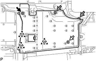
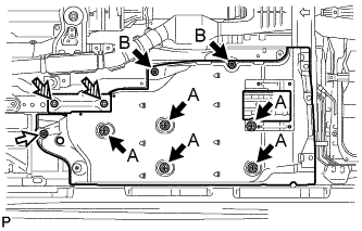
REMOVE FRONT FLOOR COVER LH
-
Detach the 4 clips and remove the front floor service hole cover.
-
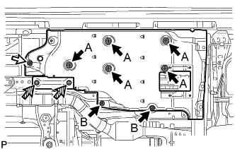
Remove the nut and 2 bolts.
Text in Illustration Clip Nut Bolt -
Loosen the 7 clips labeled A and B in the illustration, and then remove the front floor cover LH.
Tech Tips
The clips labeled A and B cannot be removed.
-
-
REMOVE FRONT FLOOR COVER RH
-
Detach the 4 clips and remove the front floor service hole cover.
-
Remove the nut and 2 bolts.
Text in Illustration Clip Nut Bolt -
Loosen the 7 clips labeled A and B in the illustration, and then remove the front floor cover RH.
Tech Tips
The clips labeled A and B cannot be removed.
-
-
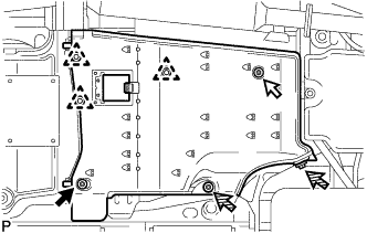
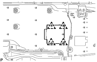
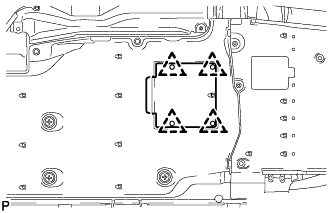
REMOVE FRONT CENTER FLOOR COVER
-
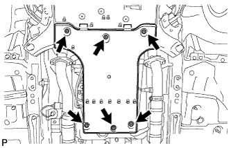
Remove the 3 screws, 2 bolts, clip and front center floor cover.
-
-
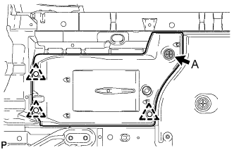
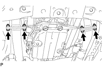
REMOVE FRONT CENTER FLOOR BRACE SUB-ASSEMBLY
-
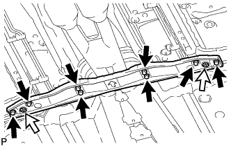
Loosen the 2 clips, and then remove the 8 bolts and front center floor brace sub-assembly.
Text in Illustration Bolt Clip Tech Tips
The clips cannot be removed.
-
-
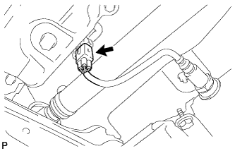
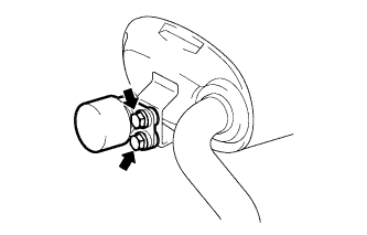
DISCONNECT HEATED OXYGEN SENSOR (for Bank 2 Sensor 2)
Note
Do not strike the metal part of the heated oxygen sensor.
-
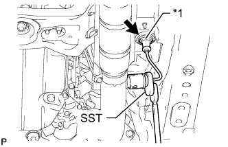
Text in Illustration *1 Grommet Disconnect the grommet from the floor panel.
-
Using SST, loosen the heated oxygen sensor, and then disconnect the heated oxygen sensor by hand.
- SST
- 09224-00010
Tech Tips
Rotate the heated oxygen sensor counterclockwise to remove it from the front exhaust pipe assembly, and record how many times it was rotated.
-
-
REMOVE FRONT EXHAUST PIPE ASSEMBLY
-
Disconnect the heated oxygen sensor connector.
-
Temporarily loosen the 8 bolts and 4 nuts on the tailpipe sides and manifold sides.
-
Remove the 4 nuts and 4 bolts from the exhaust manifold LH and exhaust manifold RH side.
Tech Tips
During removal, hold the front exhaust pipe assembly.
-
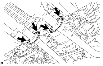
Remove the 4 bolts from the tailpipe LH and tailpipe RH side. Then remove the front exhaust pipe assembly.
Tech Tips
During removal, hold the front exhaust pipe assembly.
-
Remove the 2 gaskets from the exhaust manifold LH and exhaust manifold RH.
-
Remove the 2 gaskets from the tailpipe side.
-
-
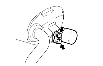
REMOVE HEATED OXYGEN SENSOR (for Bank 1 Sensor 2)
Note
Do not strike the metal part of the heated oxygen sensor.
-
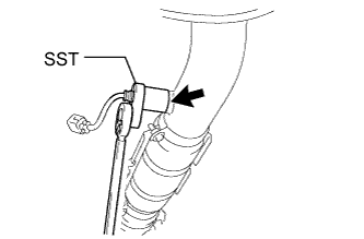
Using SST, loosen the heated oxygen sensor and then remove the heated oxygen sensor by hand.
- SST
- 09224-00010
-
-
REMOVE TAILPIPE LH
-
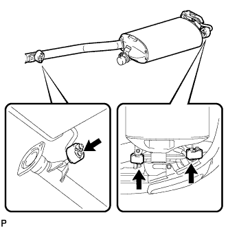
Disconnect the 3 exhaust pipe supports to remove the tailpipe LH.
-
-
REMOVE TAILPIPE RH
-
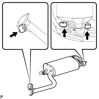
Disconnect the 3 exhaust pipe supports to remove the tailpipe RH.
-
-
REMOVE EXHAUST PIPE DAMPER
-
Remove the 2 bolts and exhaust pipe damper from the tailpipe LH.
-
Remove the 2 bolts and exhaust pipe damper from the tailpipe RH.
-
-
REMOVE NO. 1 EXHAUST PIPE SUPPORT BRACKET SUB-ASSEMBLY
-
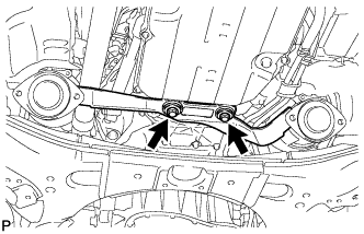
Remove the 2 bolts and No. 1 exhaust pipe support bracket sub-assembly.
-